Observation optical system and optical apparatus

a technology of optical system and optical apparatus, applied in the field of observation optical system, can solve the problems of increased manufacturing process, increased cost, and inability to perform vapor deposition at high temperature, and achieve the effect of suppressing the occurrence of surface reflection ghosts and improving transmittan

Inactive Publication Date: 2006-04-25
CANON KK
View PDF10 Cites 3 Cited by
  • Summary
  • Abstract
  • Description
  • Claims
  • Application Information

AI Technical Summary

Benefits of technology

[0016]An object of the present invention is to provide an observation optical system with which the Fresnel reflection at the surfaces of optical members is reduced to improve the transmittance and enable suppressing of the occurrence of surface reflection ghost that occur among a plurality of optical surfaces.

Problems solved by technology

However, since these materials are weak in adhesion to plastic, in many actual cases, a plastic film for improving the adhesion is formed on the surface of the plastic lens in advance, and the abovementioned anti-reflection film is applied above this plastic film.
Also, in forming an above-described anti-reflection film on an optical member made of a plastic material, since the optical member may deform due to heating, vapor deposition at high temperature could not be performed and this presented a disadvantage in terms of durability.
Thus with the prior-art methods of suppressing reflection, even if inexpensive plastic materials are used in optical members, the provision of coating lead to increases in cost as well as an increase in manufacturing processes, and an anti-reflection structure of stable quality could not be obtained in some cases.

Method used


Image

  • Observation optical system and optical apparatus
  • Observation optical system and optical apparatus
  • Observation optical system and optical apparatus

Examples


embodiment 1

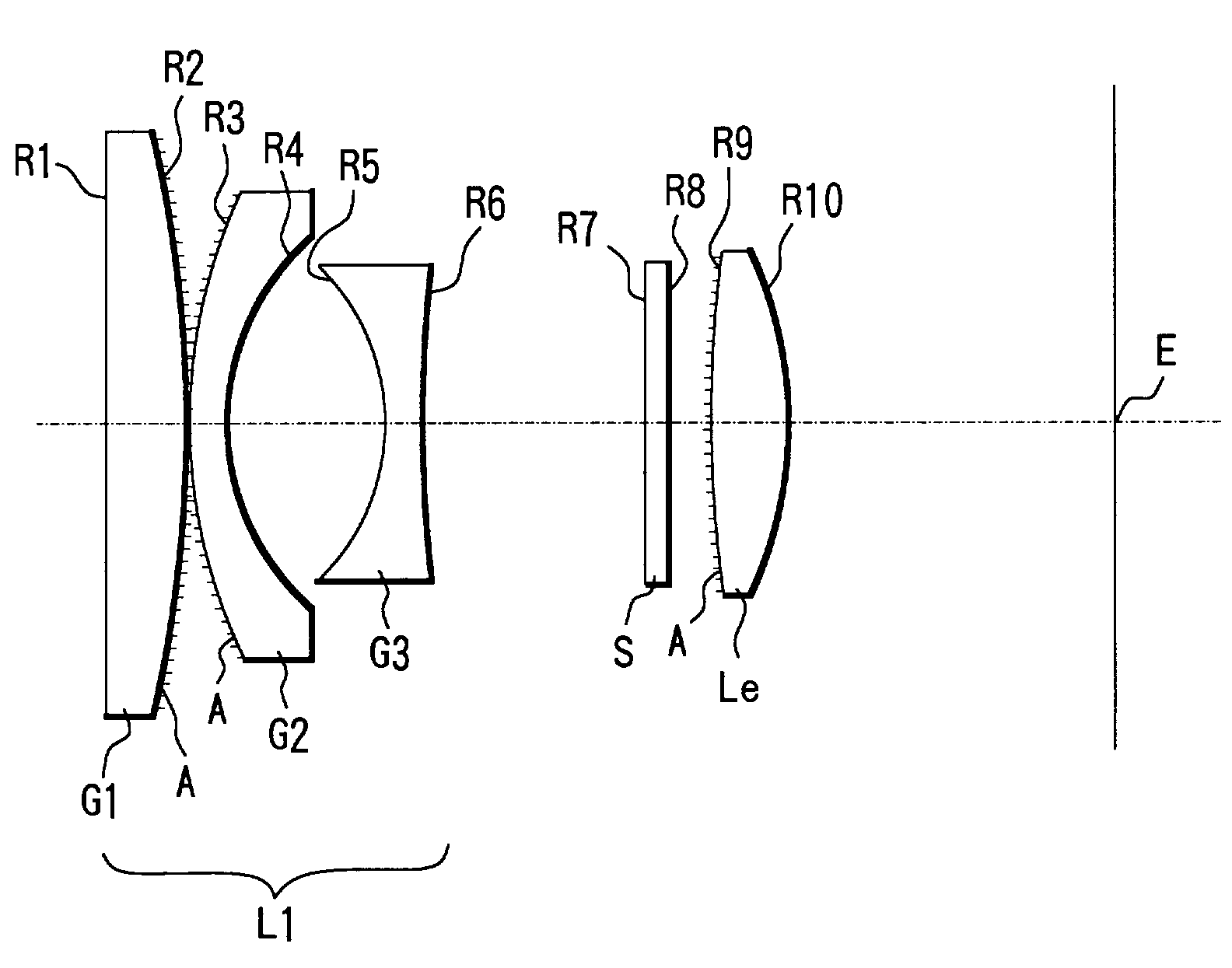
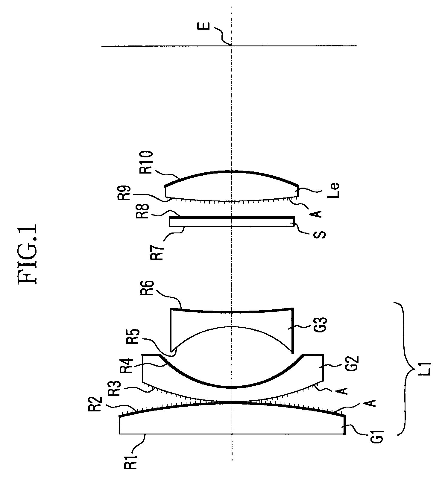
[0049]FIG. 1 shows a sectional view of the principal parts of a viewfinder optical system of Embodiment 1 of the present invention. This viewfinder optical system is a viewfinder optical system for a camera having an objective optical system separated from an image-taking optical system, and in the Figure, the left side is the object side and the right side is the side of a pupil of an observer (image plane side).

[0050]L1 denotes an objective lens unit that has a negative refractive power as a whole and comprises, in order from the object side to the image plane side, a first lens element G1, having a positive optical power (optical power is the reciprocal of the focal length of the lens element), a second lens element G2, having a negative optical power, and a third lens element G3, having a negative optical power.

[0051]Le denotes an ocular lens unit and the ocular lens unit Le comprises a single lens having a positive optical power.

[0052]The material of all of the lens elements G1...

embodiment 2

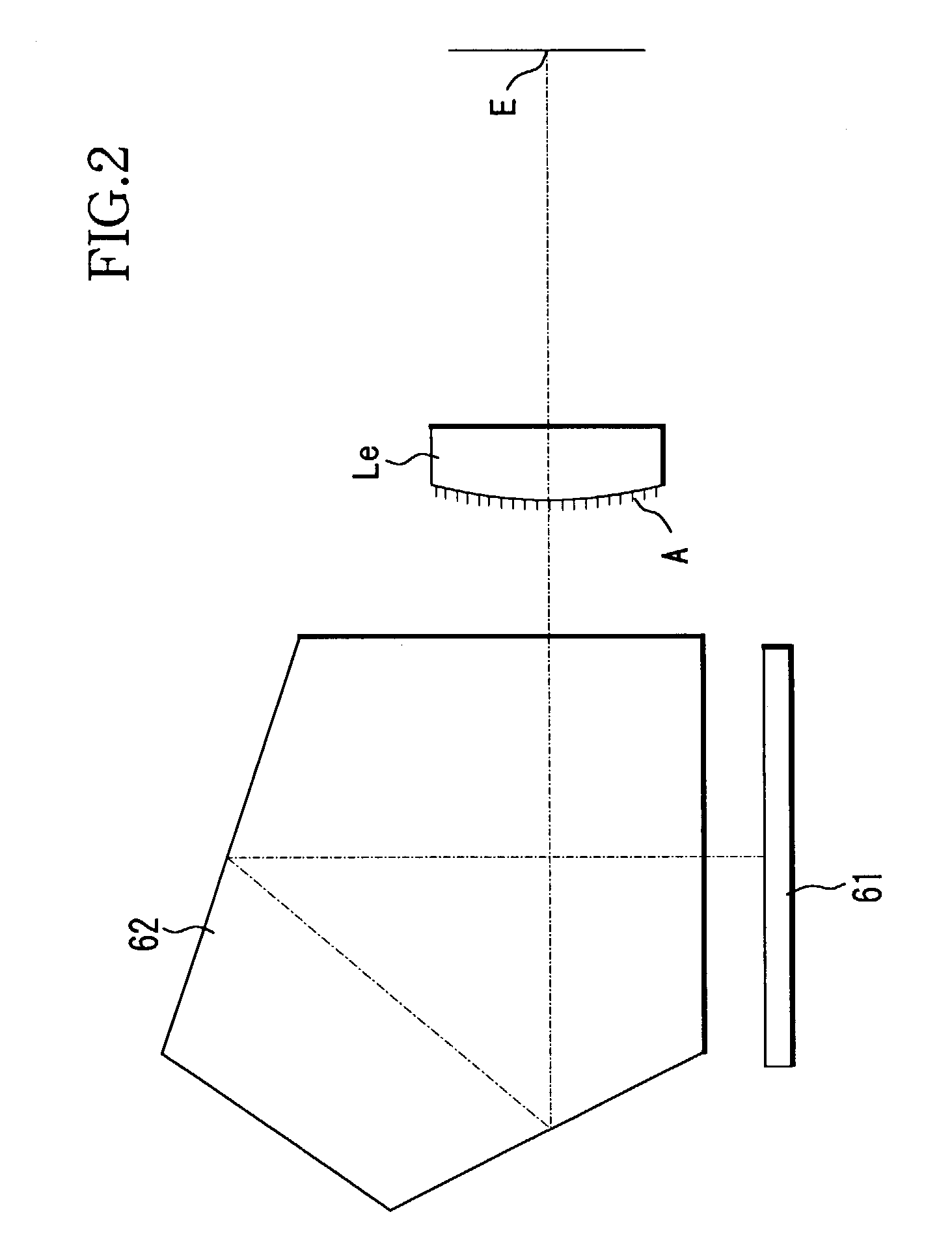
[0062]Both FIG. 2 and FIG. 3 show sectional view of the principal parts of a viewfinder optical system of a single-lens reflex camera, which is Embodiment 2 of the present invention.

[0063]The viewfinder optical system of FIG. 2 is disposed within an optical path from a focus plate 61, onto which light that has been guided by a mirror from an unillustrated image-taking optical system is made incident, to an eye point E, and is equipped with an image inversion member 62, comprising a pentaprism that performs image inversion by making use of reflection, and an ocular lens unit Le, comprising a single lens element of plastic material. With this viewfinder optical system, the same fine periodic structure A as that described with Embodiment 1 is formed at the effective optical region of the object side surface (incident surface) of the ocular lens unit Le as an integral part of the ocular lens unit (single lens element) Le.

[0064]The viewfinder optical system of FIG. 3 is disposed within a...

embodiment 3

[0068]Each of FIG. 6 and FIG. 7 shows a sectional view of the principal parts of a viewfinder optical system of Embodiment 3 of the present invention. With each of these viewfinder optical systems, an object image that is formed near a frame plate S by an objective lens unit (comprising a lens elements G1 and G2) L1 is observed from an eye point E via an ocular lens unit (comprising a single lens element) Le.

[0069]An image inversion member, comprising plastic prisms P1 and P2 that are disposed with a minute air interval d therebetween, is disposed in the optical path from the objective lens unit L1 to the ocular lens unit Le. In FIG. 6, light emerging from the prisms P1 and P2 is bent in an optical path by a high-reflection mirror M1 and guided to ocular lens unit Le, and in FIG. 7, the light emerging from the objective lens unit L1 is bent in an optical path by the high-reflection mirror M1 and guided to the prisms P1 and P2.

[0070]With each of these embodiments, at the effective op...


PUM

PropertyMeasurementUnit
grating widthaaaaaaaaaa
wavelengthaaaaaaaaaa
focal lengthaaaaaaaaaa

Abstract

An observation optical system is disclosed with which the Fresnel reflection at the surfaces of optical members can be reduced, the transmittance can be improved, and the surface reflection ghost that occur among a plurality of optical surfaces can be suppressed. The observation optical system of the present invention comprises a plurality of optical surfaces, and a fine periodic structure, with a period smaller than the wavelength of incident light, is provided at an effective optical region of at least one surface among the aforementioned plurality of optical surfaces.

Description

BACKGROUND OF THE INVENTION[0001]1. Field of the Invention[0002]The present invention relates to an observation optical system to be used as a viewfinder optical system of a still camera or video camera or to be used in binoculars, etc.[0003]2. Description of the Relating Art[0004]Previously, various methods of suppressing reflection in an optical system have been proposed. The following anti-reflection methods are known as methods for obtaining a good field of view in a viewfinder optical system of a still camera, video camera, etc.[0005]First, as an arrangement, in which an anti-reflection film of MgF2, SiO2, etc. is applied to a predetermined optical surface in order to suppress the occurrence of ghosts due to surface reflection by a lens surface, Japanese Laid-Open Patent Publication No. 1995-77730 (corresponding to U.S. Pat. No. 5,442,481) proposes a viewfinder optical system in which an anti-reflection film is applied to the surface of an objective lens.[0006]Japanese Laid-Ope...

Claims


Application Information

Patent Timeline
Patent Type & Authority Patents(United States)
IPC IPC(8): G02B3/08G03B13/06G02B1/11G02B1/118G02B5/02G02B15/20G02B17/08G02B25/00G02B27/00
CPCG02B27/0018G02B1/11
Inventor KATO, YUMIKO
Owner CANON KK
Why Eureka
Try Eureka