Compound telescope with a stationary primary objective mirror having movable collectors

a primary objective mirror and telescope technology, applied in the field of optical telescopes, can solve the problems of delayed polishing of the mirror, high cost of the mirror, and inability to move the collector, so as to achieve the effect of less cost, large cost savings, and more stability

Inactive Publication Date: 2005-04-26
POPIL NICHOLAS B
View PDF3 Cites 6 Cited by
  • Summary
  • Abstract
  • Description
  • Claims
  • Application Information

AI Technical Summary

Benefits of technology

[0026]Eliminating the large cumbersome mechanical equipment required to move the thousands of tons of heavy expensive equipment can attain large cost savings. Instead, of “riding the tube” as is done at Mt. Palomar, the observers that ride the cart of the present invention, glide on tracks around the periphery surface of the large objective mirrors in movable comfortable carts with more stability and at far less cost. Alternatively, data emitted from the primary segmented mirror can be viewed on the interior screen described above. A cost savings of over 80% can result when a comparison is made to the existing state of the art telescopes.
[0027]Another large saving can be made by eliminating most of the cost of the high structural metal and masonry walls of a typical observatory. About 30 feet of wall height would be sufficient for isolating and housing the telescope of the present invention.

Problems solved by technology

Using Hale's approach presented a number of technical problems.
And, as the size is increased, so does the cost of the mirror, until it becomes exorbitant.
But the war delayed polishing of the mirror, and it was not until Nov. 20, 1947, that the finished mirror was finally installed in the telescope on Palomar Mountain.
Unfortunately, the cost of constructing larger single-mirror telescopes increases rapidly, approximately with the cube of the diameter of the aperture.
The concept for using an ensemble of segmented mirrors dates back to the 19th century, but experiments with it had been few and small, and many astronomers doubted its viability.

Method used


Image

  • Compound telescope with a stationary primary objective mirror having movable collectors
  • Compound telescope with a stationary primary objective mirror having movable collectors
  • Compound telescope with a stationary primary objective mirror having movable collectors

Examples


Embodiment Construction

[0040]Of all the tools and instruments of science, there is none so grand or enduring as the telescope. By observing the heavens, a telescope brings us images of the past that say much about the present and provide clues about the future.

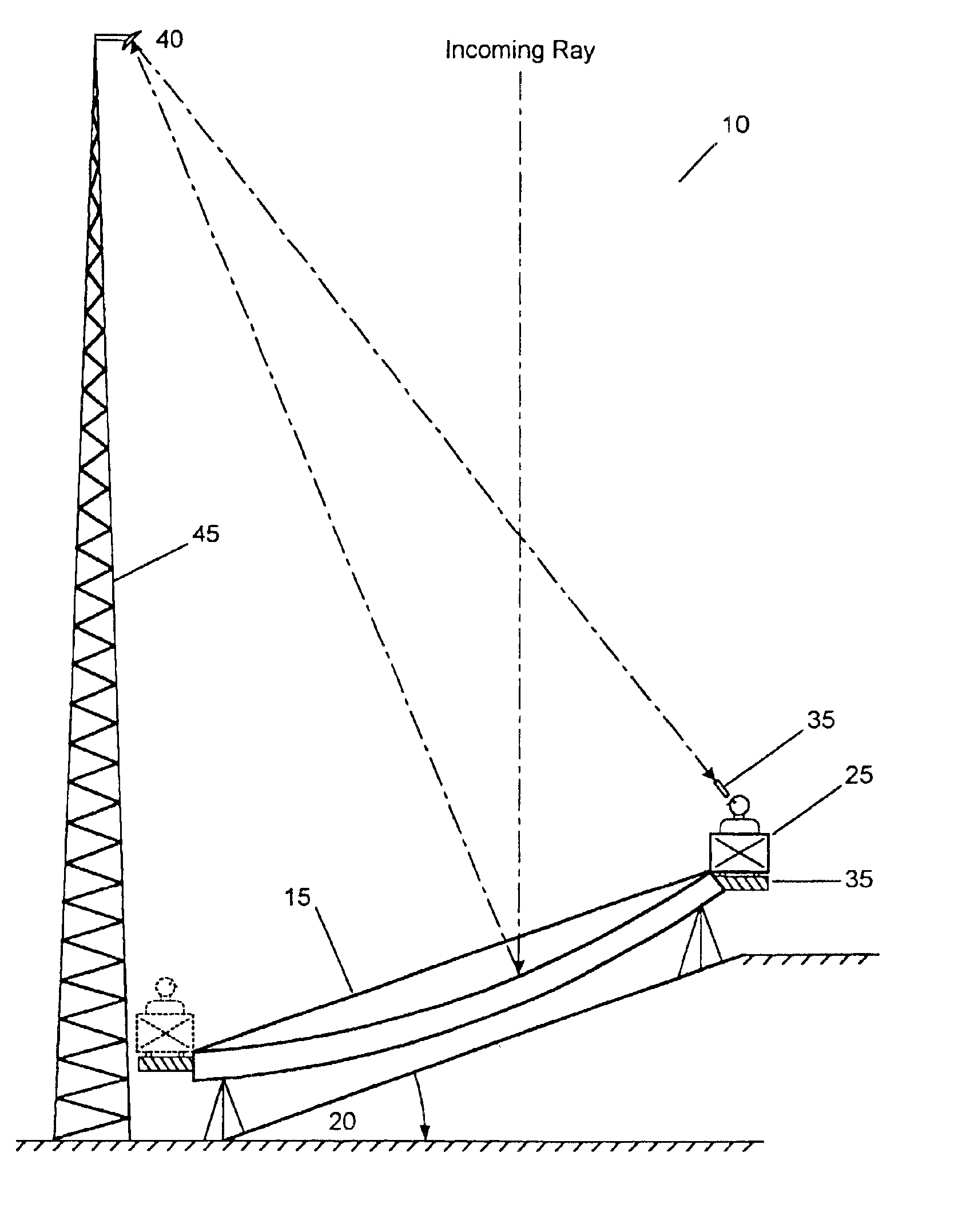
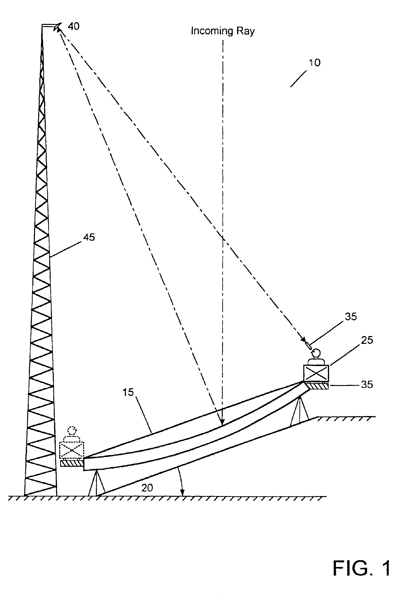
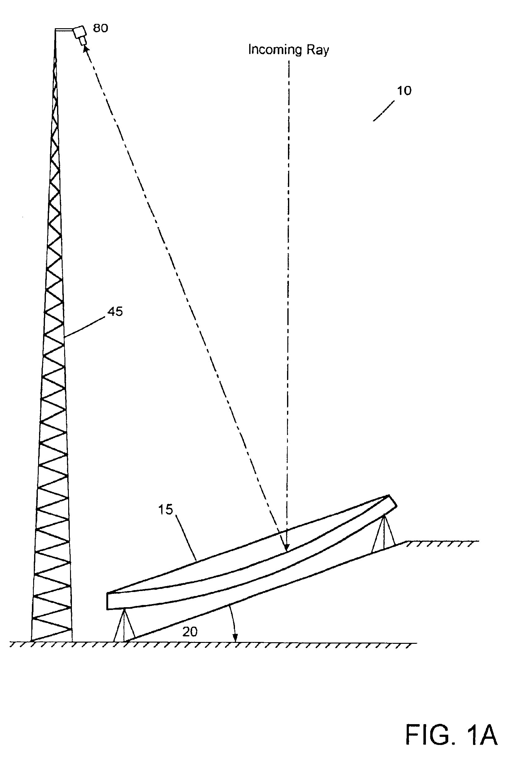
[0041]In FIG. 1, there is shown the large stationary telescope system 10. The large primary mirror 15 is set in the equatorial position to point at the North Star (for the Northern Hemisphere) at the latitude position of its location. Because of the rotation of the earth on its axis, the latitude is now constant. The angle-of-tilt 20, conforms to the latitude at the telescope site. By installing the large multi-objective lens in the equatorial position, it is always in synchronous latitude for viewing from earth, as it has been doing for the past billion years. So we can merely pick up this view by picking up the longitude with the eyepiece. Heretofore, all conventional telescopes have been moving hundreds of tons of telescope, mechanical equipment ...


PUM


Abstract

The present invention relates to a novel land based reflecting telescope having a stationary, equatorially mounted, segmented mirror comprised of a plurality of movable mirrored collectors. These movable collectors are arranged in hexagonal groups to form a multiple mirrored reflector, which comprises the stationary compound telescope. A secondary mirror mounted atop a tower at the focal point directs the image toward the observation cart. Observers ride the periphery of the stationary mirror at a rate of one revolution per day. A retractable air supported hypalon cover protects the large primary mirror structure.

Description

FIELD OF INVENTION[0001]The present invention relates primarily to optical telescopes, and more particularly to a compound telescope including a stationary primary mirror having movable collectors.BACKGROUND OF THE INVENTION[0002]In 1608, a Dutch optician named Hans Lippershey was the first to invent the telescope. The great Italian scientist Galileo Galilei, who became the first man to see the craters of the moon, and who went on to discover sunspots, the four large moons of Jupiter, and the rings of Saturn, introduced it to astronomy in 1609. Galileo's telescope was similar to a pair of opera glasses because it used an arrangement of glass lenses to magnify objects. This arrangement provided limited magnification, of about 30 times for Galileo, as well as a narrow field of view. Galileo was able to see only a fraction of the moon's face without the need for repositioning his telescope.[0003]It was in 1704 that Newton announced a new concept in telescope design whereby a curved mir...

Claims


Application Information

Patent Timeline
Patent Type & Authority Patents(United States)
IPC IPC(8): G02B17/06G02B17/00
CPCG02B17/0615
Inventor POPIL, NICHOLAS B.
Owner POPIL NICHOLAS B
Why Eureka
Try Eureka