Voltage and protection arrangement for a telephone subscriber line interface circuit

a technology of telephone subscriber line and protection arrangement, which is applied in the direction of subscriber line interface circuit, interconnection arrangement, substation equipment, etc., can solve the problems of reducing the component count and hence the cost of protection arrangemen

Inactive Publication Date: 2005-04-26
RPX CLEARINGHOUSE
View PDF19 Cites 27 Cited by
  • Summary
  • Abstract
  • Description
  • Claims
  • Application Information

AI Technical Summary

Benefits of technology

[0016]An advantage of using this method of over-voltage protection is that it is responsive to the duration of the over-voltage condition. That is, after the over-voltage condition has ended, the line circuit will rema

Problems solved by technology

The interface circuitry required to operate the FET in this mode uses less components than if the FET were oper

Method used


Image

  • Voltage and protection arrangement for a telephone subscriber line interface circuit
  • Voltage and protection arrangement for a telephone subscriber line interface circuit
  • Voltage and protection arrangement for a telephone subscriber line interface circuit

Examples


Embodiment Construction

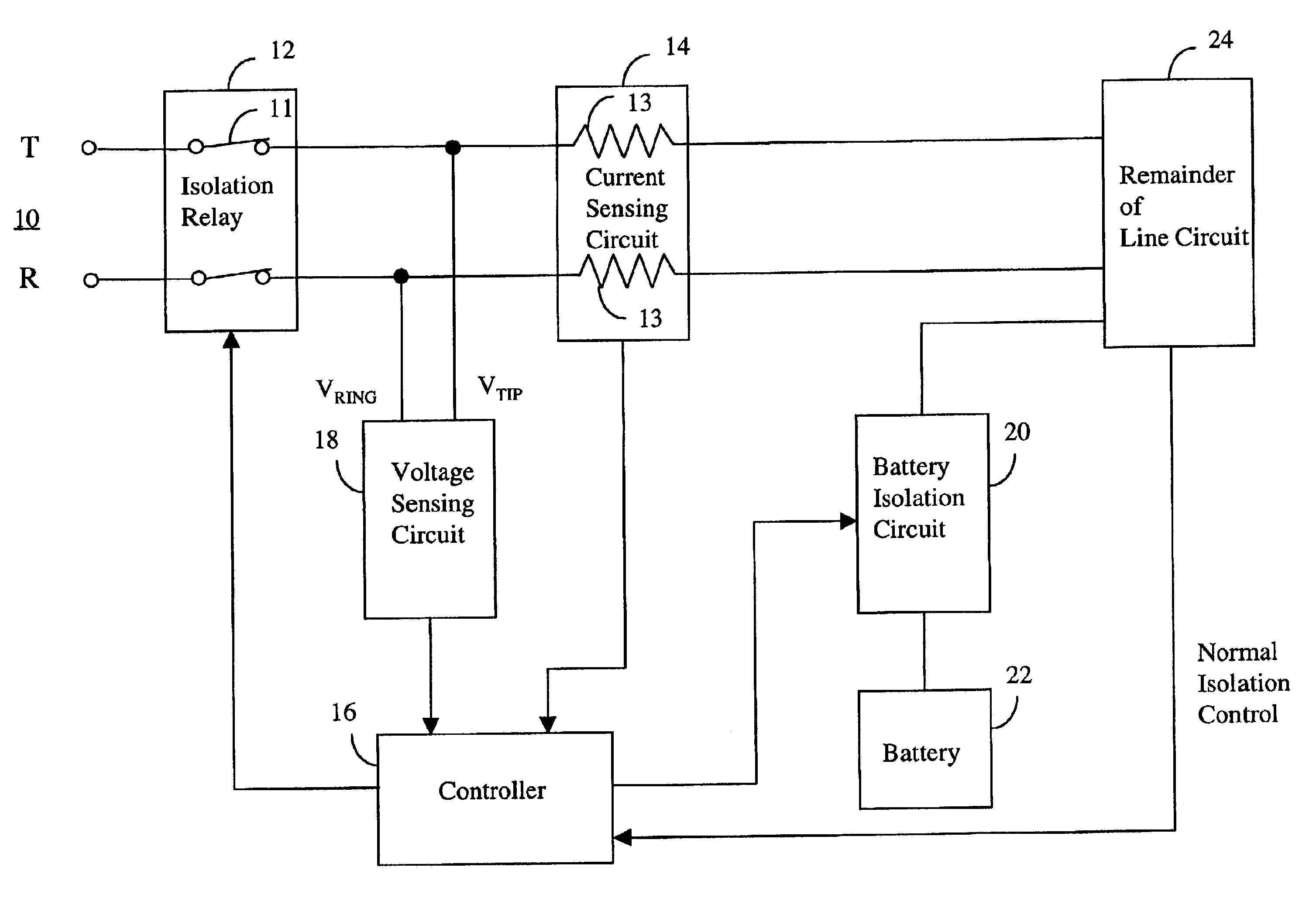
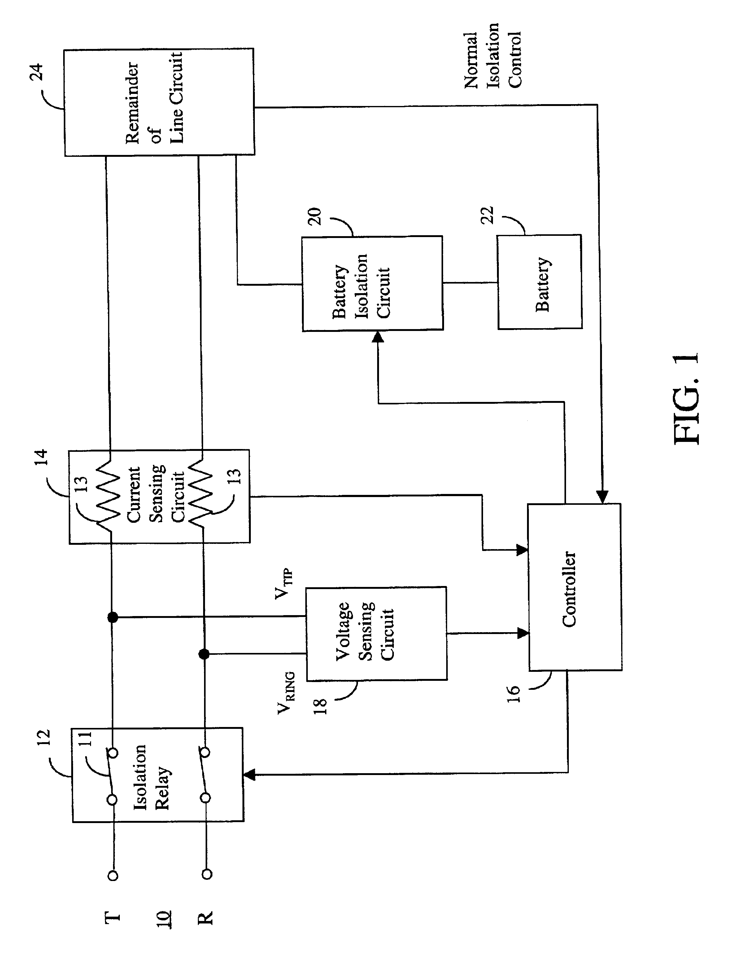
[0024]Referring to FIG. 1, a line circuit and protection arrangement is illustrated coupled to a two-wire telephone subscriber line 10 comprising tip and ring wires on sides T and R of the line 10, respectively. An isolation relay 12 is coupled in series with the tip and ring wires and provides a normally closed double pole switch 11 in series with each of the T and R sides of the line 10. A battery feed resistor 13 is connected in series between the isolation relay 12 and the remainder of the line circuit on each of the T and R sides of the line 10. A current sensing circuit 14 is coupled to the battery feed resistors 13. The isolation relay 12 is for disconnecting the line circuit from the subscriber line 10. This may be done for protecting the line circuit from an over-voltage condition that exists on the line 10, or for testing purposes. In addition, in accordance with this invention the isolation relay 12 is controlled by a controller 16 in dependence upon tip and ring voltages...


PUM


Abstract

A protection arrangement for a telephone subscriber line interface circuit is disclosed. The arrangement is particularly useful for protecting an electronic telephone set from over-voltage and over-current fault conditions. The arrangement provides a FET that operates in saturation mode to connect an office battery to the subscriber line under normal operation. The FET also provides isolation capabilities for protecting the line circuit from an over-current condition on the subscriber line. Over-voltage protection is provided by way of an isolation relay between the line circuit and the subscriber line. Both the FET and isolation relay are operated by a controller that uses timers in the methods of over-voltage and over-current protection that it performs. A further capability of the arrangement is that it resets itself after the fault condition has ended. This feature is particularly useful in the case of fault conditions of short duration.

Description

[0001]This invention relates to voltage and current protection arrangements and more particularly to protection arrangements for telephone subscriber line interface circuits, hereinafter referred to as a line circuits.BACKGROUND OF THE INVENTION[0002]Protecting a line circuit from excessive voltages and currents that can occur on the line to which it is connected is a well-known requirement. These excessive voltages and currents may be the result of relatively rare occurrences in the service lifetime of the line circuit, such as lightning strikes, or more common occurrences, such as short circuits to other lines or ground. Size, cost, and heat dissipation of the protection arrangement are important design considerations since a protection arrangement is needed for each subscriber line.[0003]A protection arrangement for a line circuit is disclosed by Rosch et al. U.S. Pat. No. 4,947,427 issued Aug. 7, 1990 and entitled “Protection Arrangement for a Telephone Subscriber Line Interface...

Claims


Application Information

Patent Timeline
IPC IPC(8): H04M3/18H04M19/00H04M3/00
CPCH04M19/001H04M3/18H04M3/005H04M2201/80
Inventor HANDFORTH, MARTIN R.HUPE, GERARD J.MCGINN, DONALD S.MEIER, ROLF G.PLANTHARA, CANUTEWONG, RAYMOND K.
Owner RPX CLEARINGHOUSE
Why Eureka
Try Eureka