
Location estimation in partially synchronized networks

a technology of partial synchronization and location estimation, applied in the direction of data switching network, distance measurement, instruments, etc., can solve the problems of low-complexity sensors without time synchronization and means to measure signal strength, and achieve the effect of longer communication range capability

Inactive Publication Date: 2005-04-26
MITSUBISHI ELECTRIC INFORMATION TECH CENT AMERICA ITA
View PDF4 Cites 12 Cited by
  • Summary
  • Abstract
  • Description
  • Claims
  • Application Information

AI Technical Summary

Benefits of technology

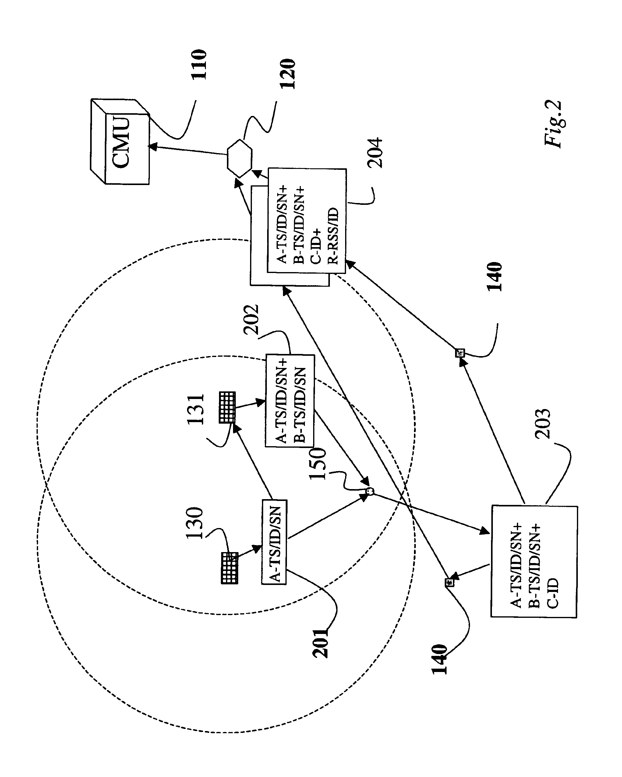
"The patent describes a method and system for locating mobile nodes in a wireless network where there are no time synchronization and the mobile nodes have limited communication ranges. The system uses stationary nodes with longer communication ranges to send signals to the mobile nodes. The time intervals it takes for the signals to travel from the stationary nodes to the mobile nodes are measured to determine the possible coordinates of the mobile node. Additionally, the received signal strengths of the mobile node are measured in two stationary nodes to provide more sets of possible coordinates. These three sets are then intersected to estimate the location of the mobile node. The technical effect of this invention is to provide a tracking system for such a network with largely varying communication ranges."

Problems solved by technology

In particular, the mobile nodes are low complexity sensors lacking time synchronization and means to measure signal strength.

Method used


Image

  • Location estimation in partially synchronized networks
  • Location estimation in partially synchronized networks
  • Location estimation in partially synchronized networks

Examples


Embodiment Construction

System Structure

[0025]My invention provides location estimation for mobile nodes in a wireless communication network lacking global synchronization. As a characteristic, the nodes for which locations are to be estimated are mobile, low-complexity, low-power, unsynchronized, and have a relatively short radio range, e.g., in the order of meters.

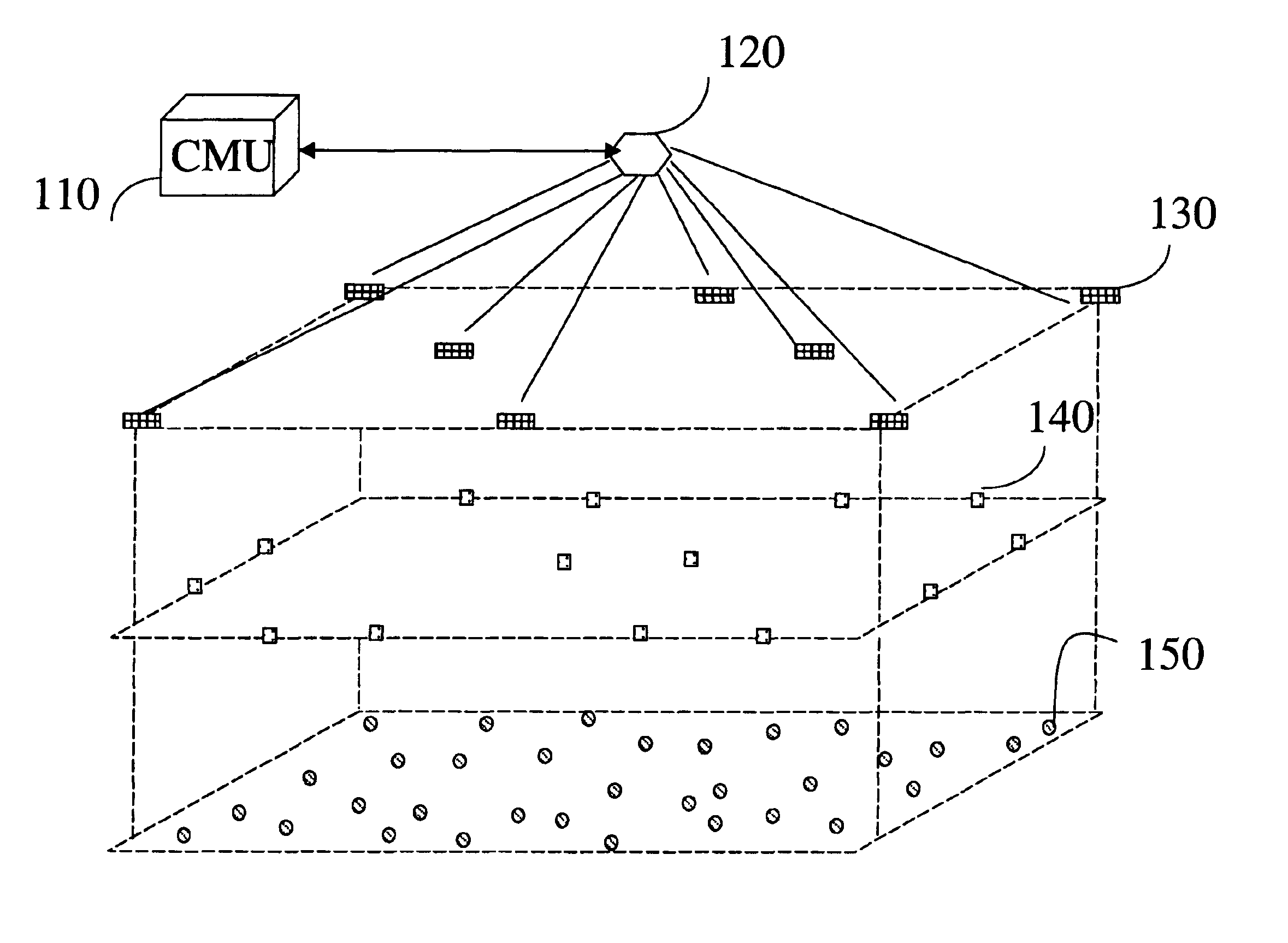
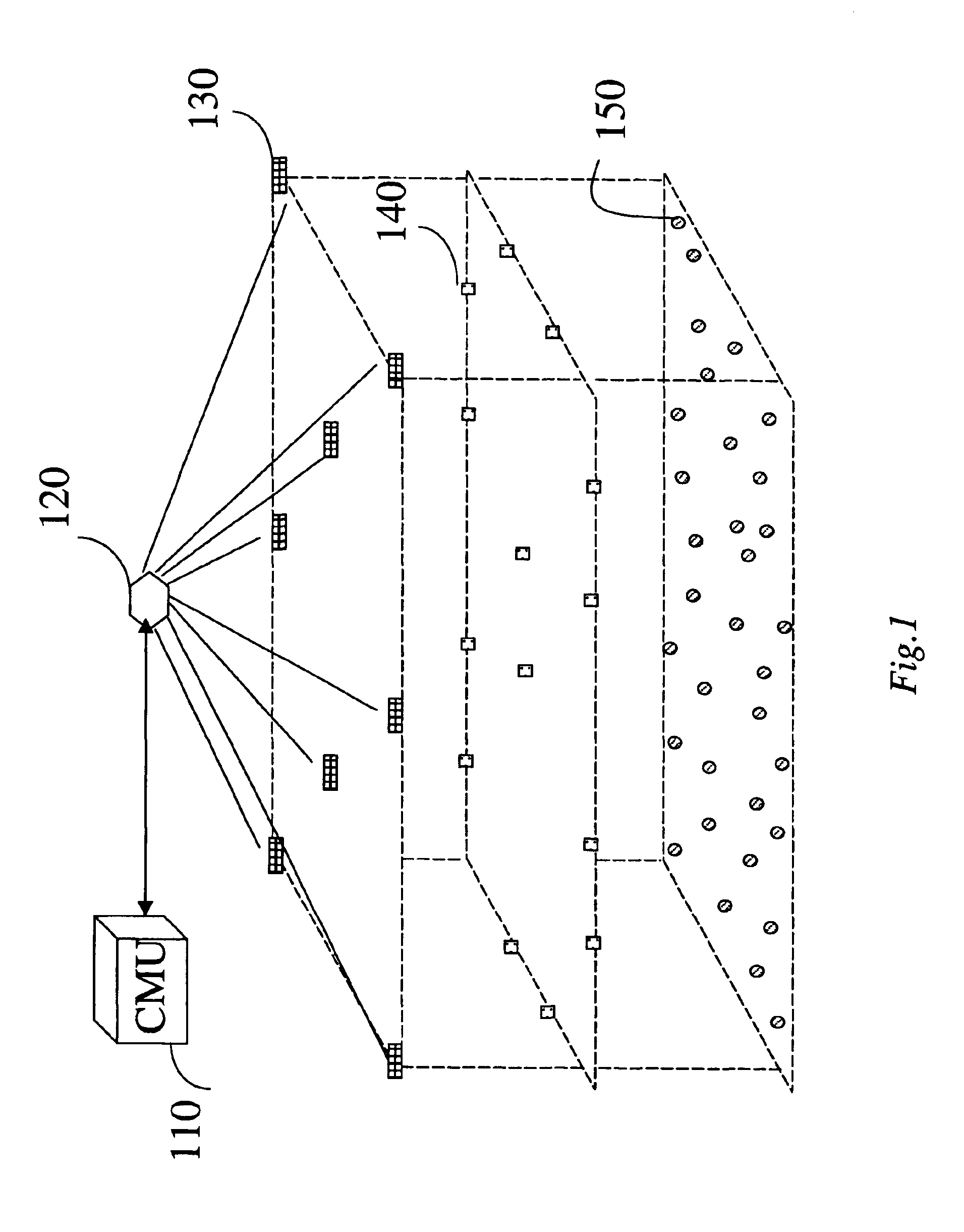
[0026]As shown in FIG. 1, my network has four types of nodes. Each node has a unique identification (ID). Each node can send and receive messages. Each message from a particular node has a sequence number (SN), thus any ID-SN uniquely identifies the node and the message. Only the position nodes have access to synchronized timing information.

[0027]The levels in FIG. 1 only indicate a hierarchy of the nodes for the purpose of this description. It should be understood that the nodes can be intermingled in a 3D environment in an arbitrary manner.

[0028]Position nodes 130 are stationary at known locations. Position nodes are time synchronized among t...


PUM


Abstract

A method locates a mobile node in a partially synchronized wireless network comprised of nodes with heterogeneous communication ranges. The time intervals it takes for messages to travel from stationary nodes at known location to a mobile node at an unknown location are measured and used to determine a set of possible coordinates of the mobile node. This time-based set of coordinates is in the form of a hyperbolic function. The received signal strengths of a message received from the mobile node is measured in two additional stationary nodes at known location. These RSS-based measurements provide two more sets of possible coordinates of the mobile node. The three sets are then intersected to estimate the location of the mobile node.

Description

FIELD OF THE INVENTION[0001]The invention relates generally to determining locations of wireless communication devices in a communication network, and more particularly to locating mobile devices in a network lacking globally synchronized timing signals.BACKGROUND OF THE INVENTION[0002]Wireless communications networks and devices are becoming smaller and smaller. For example, in piconets, the radio range of Bluetooth devices is ten meters or less. Typically, the devices operate without any centralized infrastructure. Nodes enter and exit the network at will, and the network topology is ad hoc.[0003]Another example is a wireless sensor network. Sensor networks are also used to monitor factory operation, vehicle operation, the environment, and public structures such as bridges and tunnels. Recently, the University of California, Berkeley and Intel Berkeley Research Lab demonstrated a self-organizing wireless sensor network including over 800 low-power sensor nodes, each the size of a ...

Claims


Application Information

Patent Timeline
Patent Type & Authority Patents(United States)
IPC IPC(8): G01C17/00G06F15/00G01S5/02G01S5/12G01S19/09G01S19/42H04L12/56H04W24/00H04W64/00
CPCH04W64/00G01S5/12G01S5/0289H04W24/00
Inventor SAHINOGLU, ZAFER
Owner MITSUBISHI ELECTRIC INFORMATION TECH CENT AMERICA ITA
Learn More