
Data storage apparatus

a data storage and data technology, applied in the field of data storage apparatuses, can solve the problems of increasing costs, unable to provide measurement data for analysis in an effective manner, and measurement data stored before the generation of triggers can be lost, so as to achieve the effect of storing effective data efficiently and without increasing the storage capacity of the apparatus

Inactive Publication Date: 2005-04-26
HONDA MOTOR CO LTD
View PDF6 Cites 2 Cited by
  • Summary
  • Abstract
  • Description
  • Claims
  • Application Information

AI Technical Summary

Benefits of technology

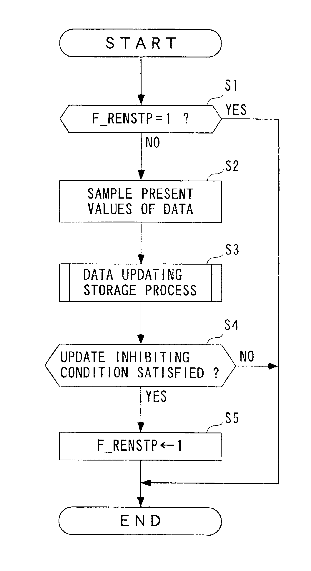
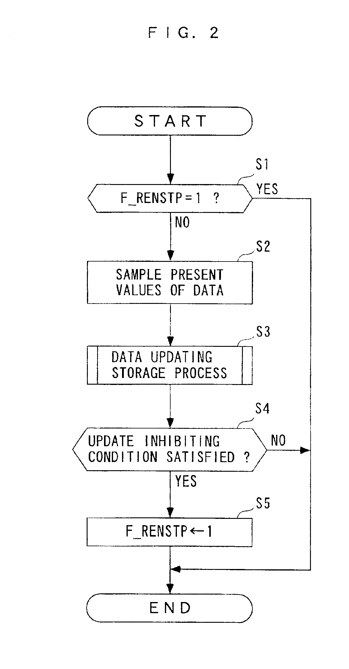
The present invention provides a data storage apparatus that can efficiently store effective data over a long term without increasing the storage capacity. The apparatus includes sampling means for sampling data in a predetermined cycle, storage means for storing a plurality of items of the data sampled, and updating means for updating the plurality of items of data to respective ones of the plurality of items of data which were sampled at later times. The storage density of data or frequency at which data is stored is higher as the sampling time of the data is later, i.e. closer to the latest sampling time. The apparatus can also inhibit updating of data when a predetermined update inhibiting condition is satisfied. The predetermined updating cycles are set to respective values obtained by multiplying a predetermined value by 2n. The storage means comprises a plurality of storage areas associated with the predetermined updating cycles. The technical effects of the invention include efficient data storage, reduced storage capacity requirements, and improved data analysis for malfunctions or failures.

Problems solved by technology

However, the conventional data storage apparatus, in which before generation of the trigger, measurement data items are recorded in the thinned manner at a rate of one data item per five input data items, and only upon generation of the trigger, three consecutive measurement data items input immediately before the generation of the trigger are recorded, cannot provide the measurement data for analysis in an effective manner.
Further, since measurement data items are continuously recorded once the trigger has been generated, if the storage capacity of the ring buffer memory is small, measurement data stored before the generation of the trigger can be lost.
However, this solution makes it necessary to increase the storage capacity of the ring buffer memory, which results in an increase in costs.

Method used


Image

  • Data storage apparatus
  • Data storage apparatus
  • Data storage apparatus

Examples


Embodiment Construction

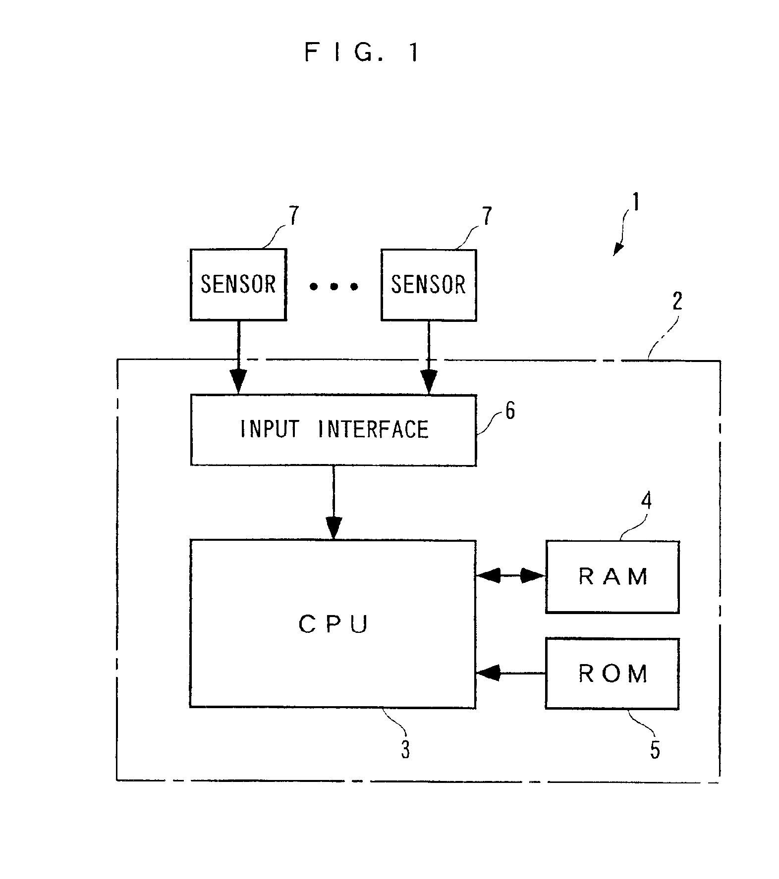
[0026]The invention will now be described in detail with reference to the drawings showing a preferred embodiment thereof. Referring first to FIG. 1, there is schematically shown the arrangement of a data storage apparatus according to an embodiment of the present invention. The data storage apparatus 1 is used for analyzing a malfunction condition which has occurred in the engine or power system of a vehicle, none of which are shown.

[0027]As shown in the figure, the data storage apparatus 1 is formed by an ECU 2 (sampling means, storage means, updating means, inhibiting means), which is implemented by a microcomputer including a CPU 3, a RAM 4 (storage means), a ROM 5, and an input interface 6. Connected to the input interface 6 are a plurality of sensors 7 (only two of which are shown). The sensors 7 detect respective parameters (e.g. a rotational speed of an output shaft of an automatic transmission and the like) indicative of operating conditions of the engine and power system o...


PUM


Abstract

A data storage apparatus includes a sampling device for sampling data in a predetermined cycle, and a storage device for storing a plurality of items of the data sampled by said sampling device. The data storage apparatus also includes an updating device for updating the plurality of items of the data stored in said storage device to respective ones of the plurality of items of the data, which were sampled at later times than the plurality of items of the data were stored, in respective predetermined updating cycles which are shorter than the updating cycles of the plurality of items of the data which were sampled at respective earlier times.

Description

BACKGROUND OF THE INVENTION[0001]1. Field of the Invention[0002]This invention relates to a data storage apparatus for storing data, such as measurement data input from the outside.[0003]2. Description of the Prior Art[0004]Conventionally, a data storage apparatus of this kind has been proposed e.g. by Japanese Laid-Open Patent Publication (Kokai) No. H06-18293. The data storage apparatus includes an A / D converter circuit, a CPU, a ring buffer memory, and recording means. In this data storage apparatus, a process for recording measurement data is executed as follows: First, the A / D converter circuit converts a measurement data item input from the outside to a digital measurement data item. Then, the digital measurement data item is temporarily stored in the ring buffer memory, and at the same time it is determined whether or not a trigger has been generated. If no trigger has been generated, it is determined whether or not the present measurement data item stored in the ring buffer ...

Claims


Application Information

Patent Timeline
Patent Type & Authority Patents(United States)
IPC IPC(8): G01D9/00
CPCG01D9/005
Inventor NISHINA, MASATOSHIMACHINO, HIDEKI
Owner HONDA MOTOR CO LTD
Learn More