Method and system for autonomously resolving a failure

a technology of failure and auto-resolution, applied in the field of diagnostics and repairs, can solve the problems of difficult to precisely identify a failed component or other cause of the failure condition, and the effect of failure on the system or subsystem is often neither readily apparent nor easily apparent, and the effect of failure on the system or subsystem is difficult to be precisely identified

Inactive Publication Date: 2005-05-03
GENERAL ELECTRIC CO
View PDF7 Cites 16 Cited by
  • Summary
  • Abstract
  • Description
  • Claims
  • Application Information

AI Technical Summary

Benefits of technology

[0010]A diagnostics system is also provided that receives the data from the sensor and isolates a pending and / or occurring failure. A processor is connected to the diagnostics system to determine a self-healing technique for the failure. The self-healing technique comprises a self-healing control technique, a redundancy technique, and / or an automatic fix technique.

Problems solved by technology

The diagnosis, repair, maintenance and / or other servicing of generally complex equipment, such as mobile assets that may include on-road and off-road vehicles, ships, airplanes, railroad locomotives, trucks, and other forms of complex equipment including industrial equipment, consumer appliance equipment, medical imaging equipment, equipment used in industrial processes, telecommunications, aerospace applications, power generation, etc. involves extremely complex and time consuming processes.
Conducting the diagnostics at the service yard for all faults detected may extend the overall amount of time the vehicle is out of service, especially when considering the complexity of locomotive systems and subsystems, it is sometimes difficult to precisely identify a failed component or other cause of the failure conditions.
This may be because the effects or problems that the failure has on the system or subsystem are often neither readily apparent in terms of their source nor unique.
Sometimes the recommended fix for a problem may not resolve the problem due to the complexity of the problem and / or diagnostic efforts.
However, with more complex problems these efforts may be more difficult and may lead to the inefficient operation or underutilization of a locomotive or fleet of locomotives.
However, more complex equipment and process diagnostics seldom have such simple correspondences.
Consequently, recommended fixes may be made that do not solve a problem immediately or completely.
This may not be determined for sometime after the fix was executed, leading to the potential for recommending the same improper fix when that problem is next identified.

Method used


Image

  • Method and system for autonomously resolving a failure
  • Method and system for autonomously resolving a failure
  • Method and system for autonomously resolving a failure

Examples


Embodiment Construction

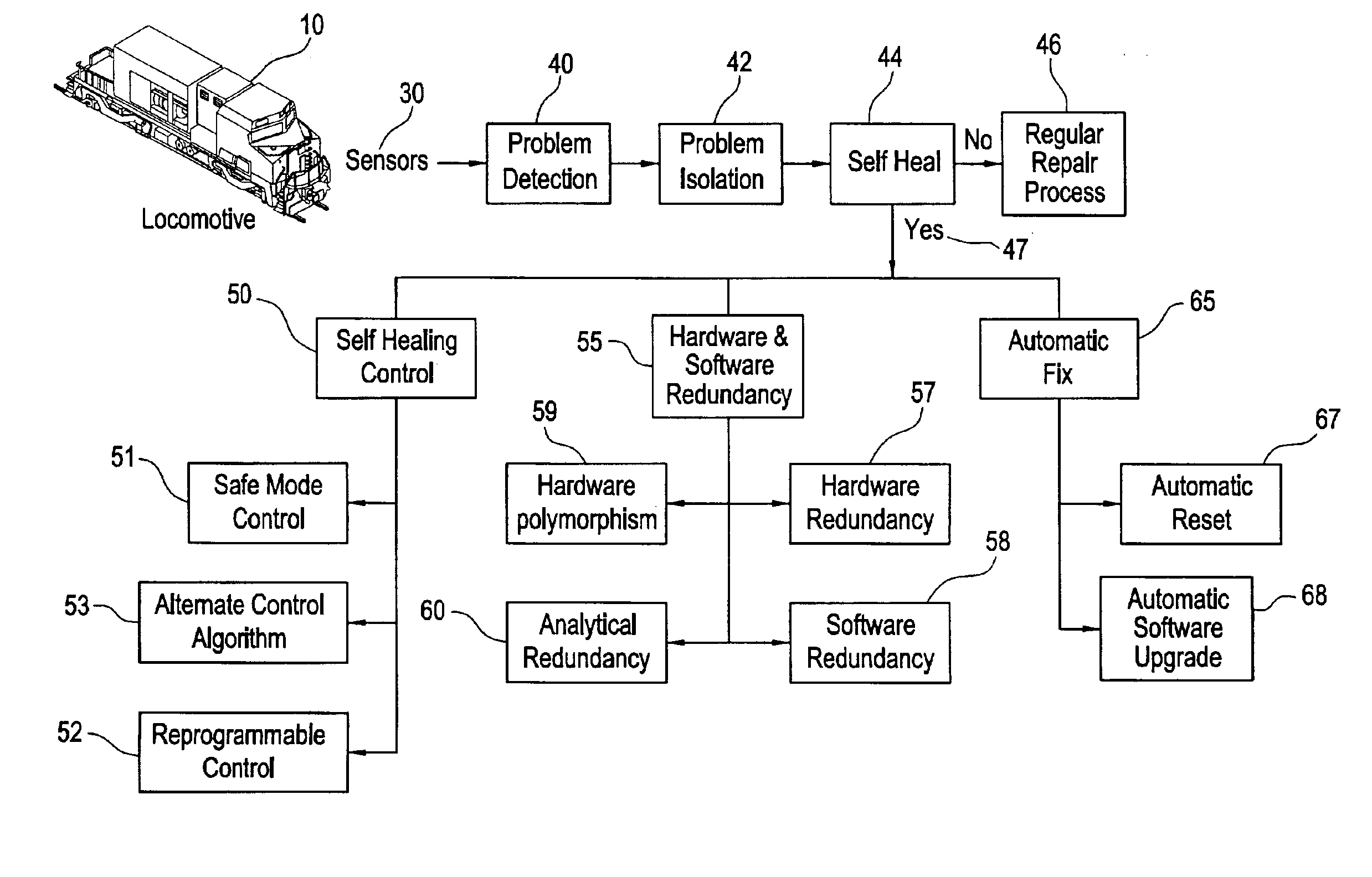
[0017]With reference to the figures, exemplary embodiments of the invention will now be described. The scope of the invention disclosed is applicable to a plurality of systems, machines, and / or processes. Thus, even though embodiments are described specific to a mobile asset, in this case a locomotive, this invention is also applicable to other systems, machines, and / or processes, which comprise components and subsystems which may fail over time. Thus the terms system, machine, process, component, and subsystem can be used interchangeably. Likewise, even though the present invention is disclosed towards fixing pending faults, it is also applicable to correcting current faults.

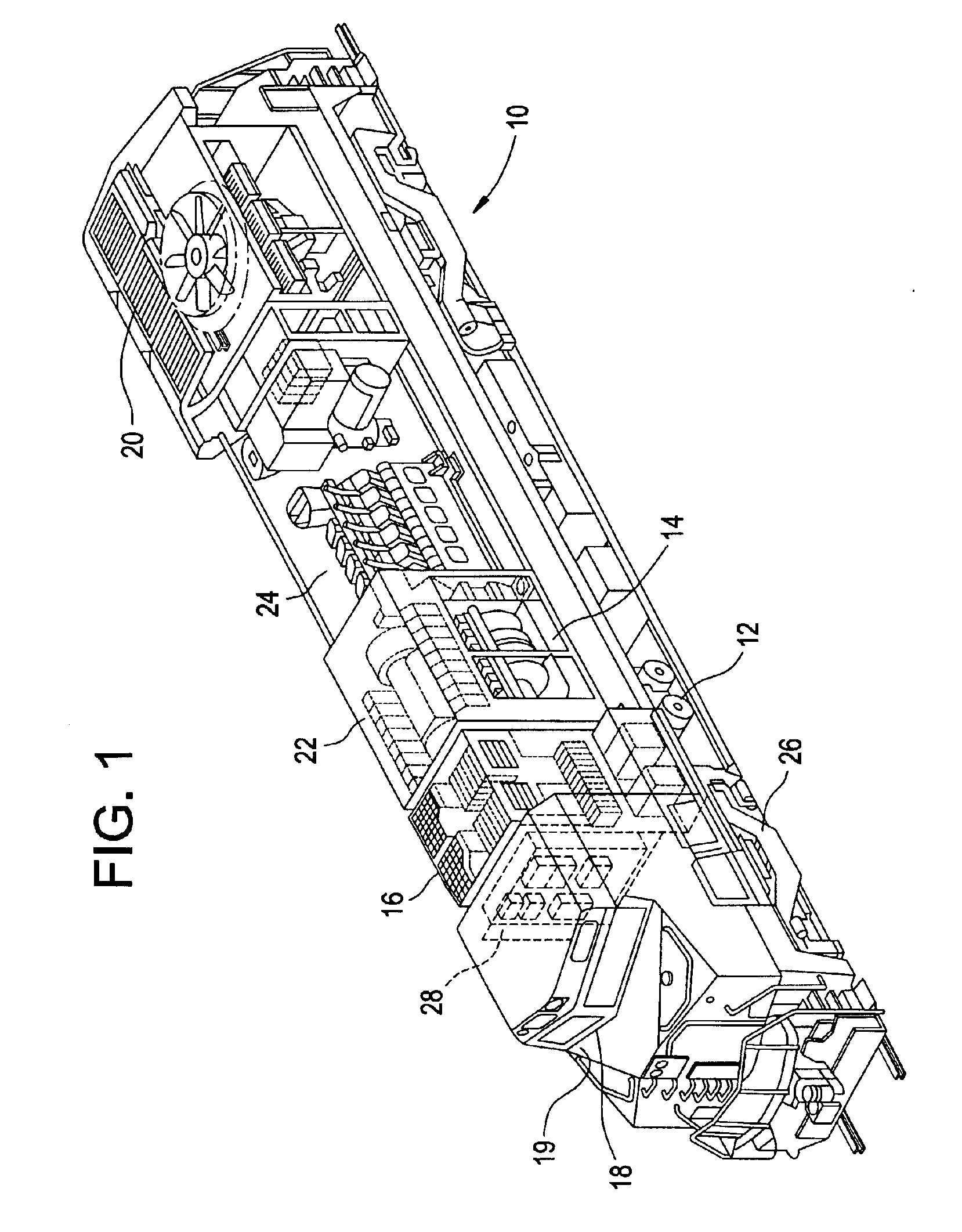
[0018]FIG. 1 is an illustration of an exemplary locomotive. The locomotive 10 may be either an AC or DC locomotive. The locomotive 10 is comprised of several complex systems, such as, but not limited to, an air brake system 12, an auxiliary alternator system 14, an intra-consist communications systems 18, a cab...


PUM


Abstract

In a railroad locomotive having a plurality of systems which collectively are used for locomotive operations, a method of self-healing a system of the plurality of systems comprising monitoring operational conditions of the system, detecting at least one of a pending and a current failure, determining a self-healing procedure to correct the failure, and applying the self-healing procedure comprising at least one of a safe mode technique, a redundancy technique, and an automatic configuration technique.

Description

BACKGROUND OF THE INVENTION[0001]This invention generally relates to diagnostics and repair, and more particularly to a method and system for correcting a malfunction or breakdown of a machine, such as a locomotive, a system, and / or a process.[0002]The diagnosis, repair, maintenance and / or other servicing of generally complex equipment, such as mobile assets that may include on-road and off-road vehicles, ships, airplanes, railroad locomotives, trucks, and other forms of complex equipment including industrial equipment, consumer appliance equipment, medical imaging equipment, equipment used in industrial processes, telecommunications, aerospace applications, power generation, etc. involves extremely complex and time consuming processes. In the case of transportation equipment, such as a locomotive and a fleet of locomotives, the efficient and cost-effect operation of a vehicle or fleet of vehicles demands minimization of the number of vehicle failures while in use, minimization of v...

Claims


Application Information

Patent Timeline
Patent Type & Authority Patents(United States)
IPC IPC(8): B60L3/00B61L15/00
CPCB60L3/0023G05B23/0286B61L15/0081B60L2200/26
Inventor JAMMU, VINAY BHASKARBHARADWAJ, RAJ MOHAN
Owner GENERAL ELECTRIC CO
Why Eureka
Try Eureka