Pivotable bulb mounted foil for sailboats

a sailboat and bulb technology, applied in the field of sailing yachts, can solve the problems of increased drag, wetted surface drag, limited system use on a fixed keel, etc., and achieve the effect of providing lateral resistance in the water, low water resistance, and providing lateral resistan

Inactive Publication Date: 2005-05-03
LORD DOUGLAS W
View PDF13 Cites 14 Cited by
  • Summary
  • Abstract
  • Description
  • Claims
  • Application Information

AI Technical Summary

Benefits of technology

[0012]A sailing boat apparatus has a boat hull having a keel having two sides and extending from the bottom of the hull. The keel has an elongated ballast bulb thereon. A rotatable foil is attached to the keel bulb and forms an integral part of the bulb when in a nested position and is rotatable about a generally perpendicular axis to the keel to extend the foil on both sides of the keel into an open operative position. A control member, which may be either a control shaft or cables or the like, extends through a channel in the hull and keel and is operatively attached to the foil to rotate the foil from a nested position, forming part of the bulb, to the operative position to provide lateral resistance in the wate

Problems solved by technology

If a canting keel is used however, some means must be found to augment the area required by a sailboat for lateral resistance since, as the keel cants, it presents less surface area capable of generating resistance to leeway.
T

Method used


Image

  • Pivotable bulb mounted foil for sailboats
  • Pivotable bulb mounted foil for sailboats
  • Pivotable bulb mounted foil for sailboats

Examples


Embodiment Construction

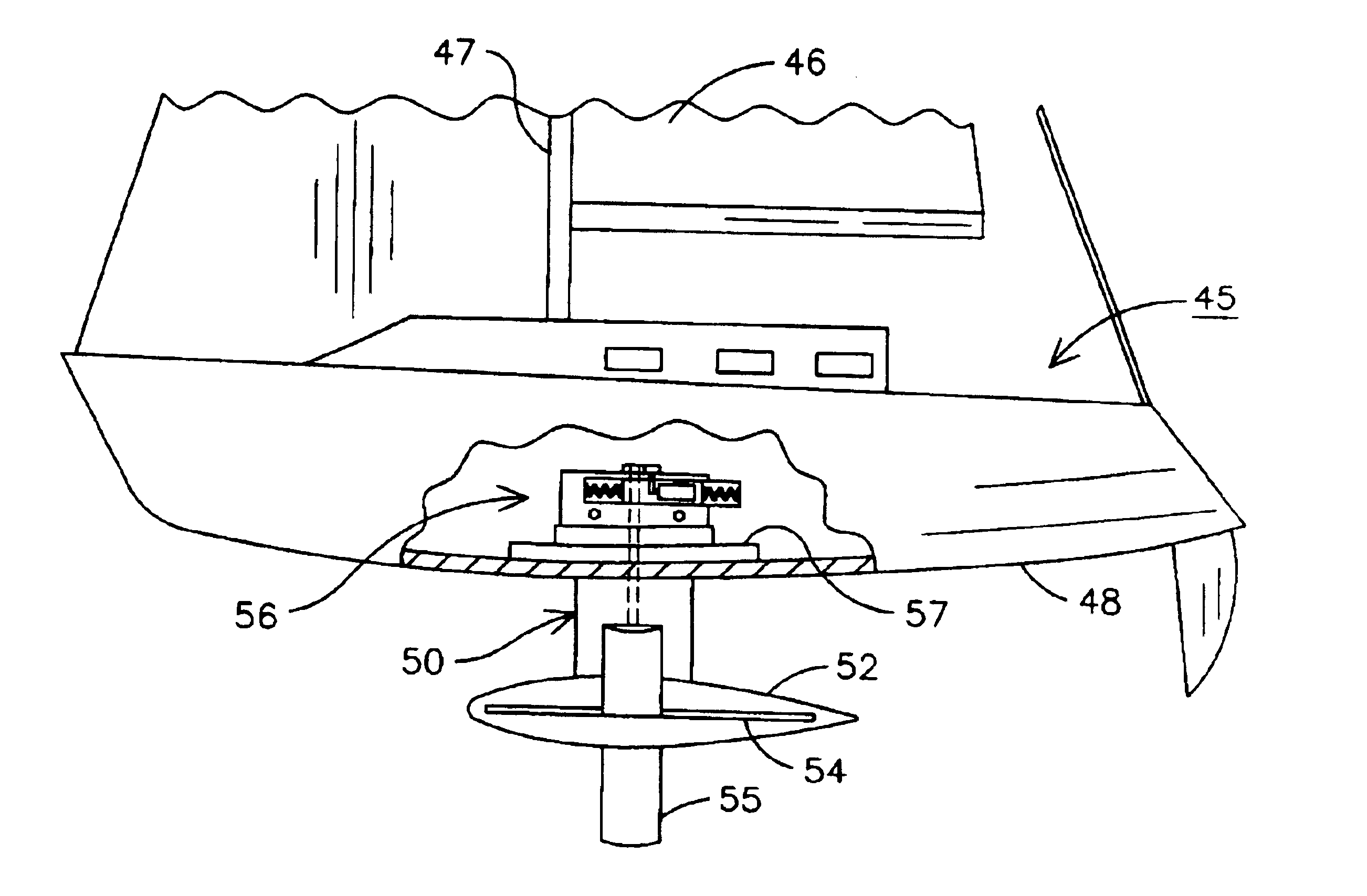
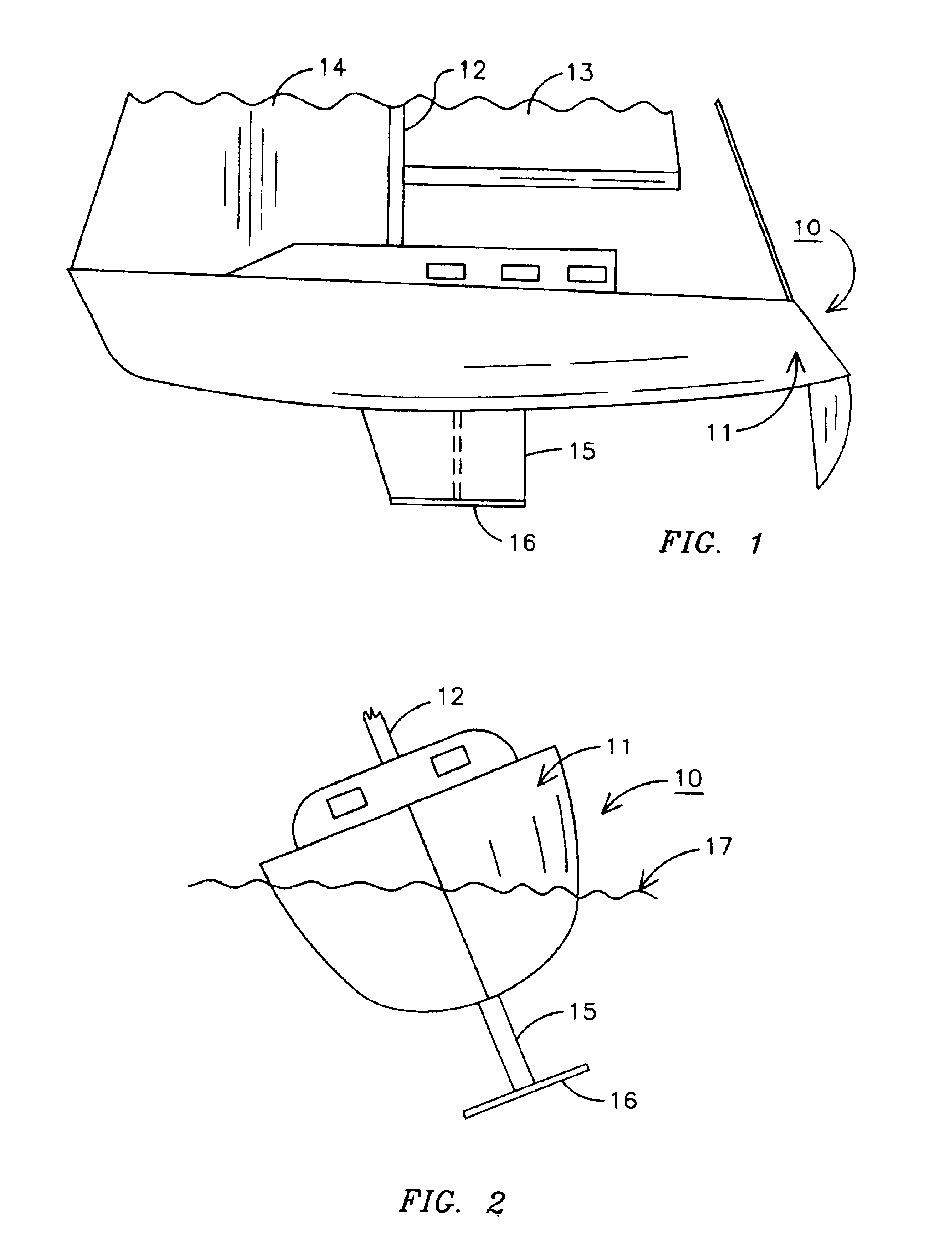
[0025]Referring to the drawings and especially to FIGS. 1 and 2, a sailboat 10 is illustrated having a hull 11 and a mast 12 supporting a sail 13 and 14. The sailboat 10 hull 11 has a keel 15 protruding from the bottom thereof which is illustrated having a rotating foil 16 extending from the bottom. FIG. 2 illustrates the sailboat 10 in water 17 listing to one side and shows how the foil 16 when in an operative position provides lateral resistance to the hull. FIGS. 1 and 2 illustrate how an existing sailboat can be modified to incorporate the present invention.

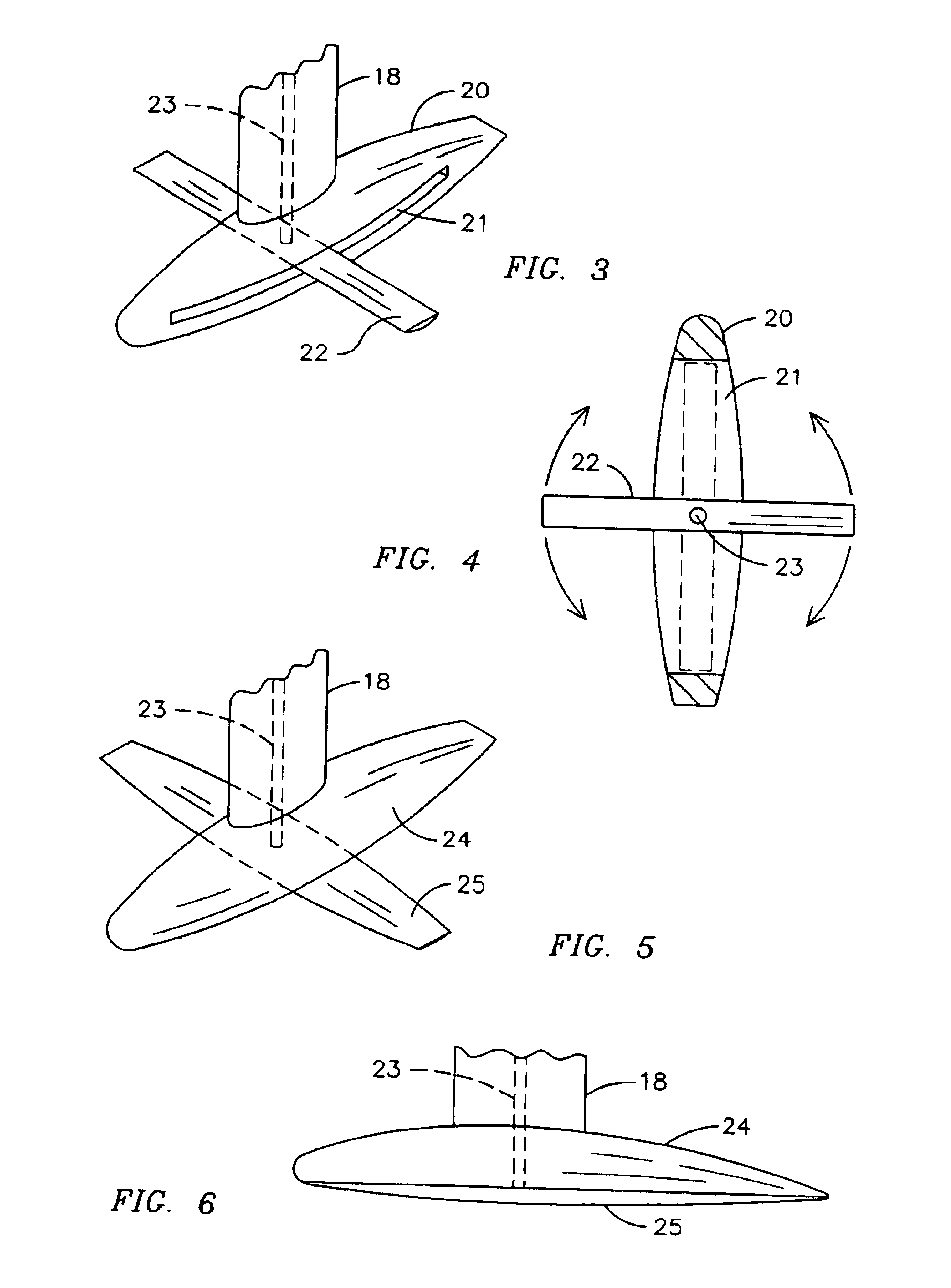
[0026]Turning to FIGS. 3 and 4, a keel 18 is illustrated having a bulb 20 attached to the bottom thereof. The bulb 20 has an elongated cutout 21 having a foil 22 mounted therein. A shaft 23 is seen extending through the keel 18 and into the bulb 20 and being attached to the foil 22. The shaft 23 extends through the hull of the sailboat where it can be rotated to move the foil 22 into and out of position within the slotted are...


PUM


Abstract

A pivotable deployable bulb mounted foil apparatus for a sailboat can pivot a foil mounted within a keel bulb remotely as needed to provide lateral resistance for the sailboat. The foil or foils can be rotated between a nested position for greater speed when the foils are not needed for lateral resistance in the water to an extended or operative position when needed for lateral resistance. The pivotal bulb mounted foil is especially adapted for use with a canting keel where the sailboat loses its lateral resistance from the keel when the keel is canted.

Description

BACKGROUND OF THE INVENTION[0001]The present invention relates to a sailing yacht and especially to a pivotally deployable bulb mounted foil for the keel of a sailing yacht which can pivot a foil mounted within a keel bulb remotely as needed to provide lateral resistance for the sailboat.[0002]The use of canting keels on sailing yachts is being widely used around the world because by using hydraulics to “cant” a keel to weather, a boat can develop large extra amounts of righting moment and therefore power to carry sail which translates directly to speed.[0003]If a canting keel is used however, some means must be found to augment the area required by a sailboat for lateral resistance since, as the keel cants, it presents less surface area capable of generating resistance to leeway. Several techniques have been employed to compensate for the loss of lateral resistance. It has been suggested to use twin fore and aft rudders to develop all lateral resistance, reducing the keel to just a...

Claims


Application Information

Patent Timeline
IPC IPC(8): B63B39/00B63B39/06B63B41/00
CPCB63B1/30B63B41/00B63B39/06B63B2039/065B63B1/28
Inventor LORD, DOUGLAS W.
Owner LORD DOUGLAS W
Why Eureka
Try Eureka