
Sewer relief valve with integral disinfectant means

a technology of disinfectant means and sewer relief valves, which is applied in the direction of valve actuation floats, valve operating means/release devices, functional valve types, etc., can solve the problems of sewer collection line blockage, effluent on the ground can create a health hazard, and the lower floors can be flooded with sewer water

Active Publication Date: 2005-05-03
HART JR JAMES R
View PDF12 Cites 22 Cited by
  • Summary
  • Abstract
  • Description
  • Claims
  • Application Information

AI Technical Summary

Benefits of technology

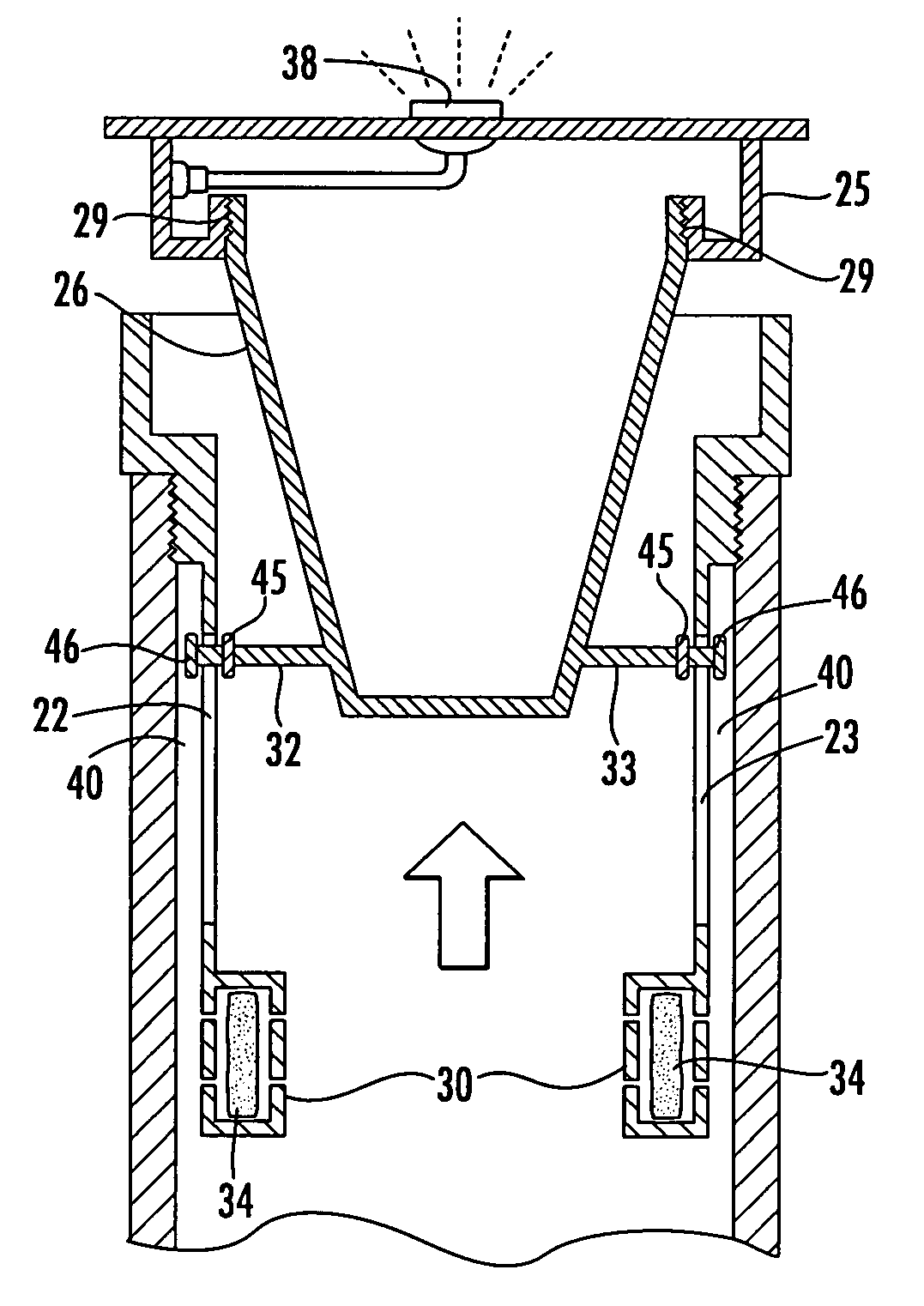
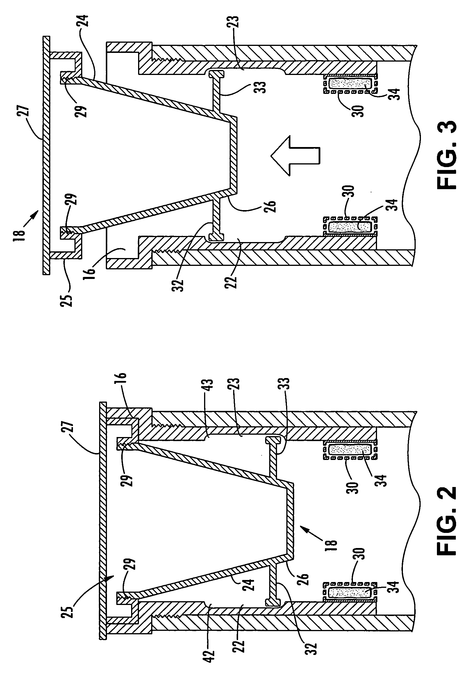
"The invention is a sewer relief valve assembly for a sewer clean out that prevents interior sewer flooding by providing an exterior valve outlet to release pressurized fluids. It also includes a water-soluble composition to treat overflow fluids discharged through the clean out, a light-emitting diode for easy identification of overflow, and an alarm means to alert of an overflow. The assembly has a cylindrical sleeve with a valve means and a perforated compartment containing a water-soluble disinfectant and dye composition. It can also include a sensing means and an alarm means activated when the valve is in the open position. The assembly provides a convenient and effective solution for preventing sewer flooding during clean out procedures."

Problems solved by technology

Due to the lack of pressure, blockages can occur in the sewer collection line, which can have the very unpleasant result of sewer water backing up in sinks, toilets, and bathtubs.
This is a particular problem for multi-story buildings, since the sewer lines on the lower floor can become clogged while higher stories continue to empty water into the sewer line, which can cause the lower floors to be flooded with sewer water.
While it is certainly preferable that the sewage backflow overflow in an outdoor environment rather than inside, the presence of the effluent on the ground can create a health hazard.
Children and pets in particular can easily come into contact with the unsanitary ground area.

Method used


Image

  • Sewer relief valve with integral disinfectant means
  • Sewer relief valve with integral disinfectant means
  • Sewer relief valve with integral disinfectant means

Examples


Embodiment Construction

[0028]Although the invention will be described in terms of a specific embodiment, it will be readily apparent to those skilled in this art that various modifications, rearrangements, and substitutions can be made without departing from the spirit of the invention. The scope of the invention is defined by the claims appended hereto.

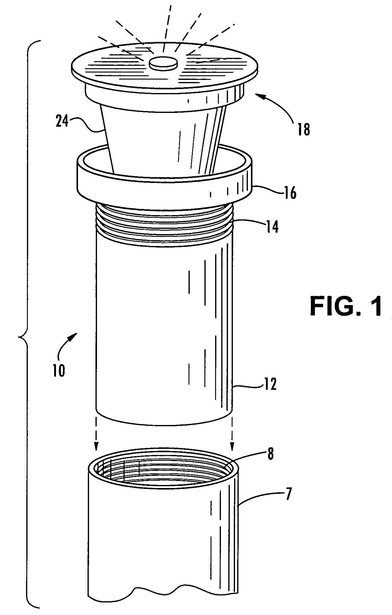
[0029]FIG. 1 is an exploded view of the instant invention in which the sewer relief valve assembly 10 according to a preferred embodiment of the invention is shown disassembled from clean out pipe 7. The clean out pipe 7, typically four inch PVC pipe, is vertically oriented and extends from the sewer pipe line to a point just above the ground. The clean out pipe 7 is generally provided with a removable threaded plug which engages with the interior threads 8 of the clean out pipe 7. In FIG. 1, the threaded plug has been removed to permit installation of the device 10 into the clean out pipe 7.

[0030]The device 10 includes a cylindrical sleeve 12 dimensioned ...


PUM


Abstract

A sewer relief valve assembly comprises a cylindrical sleeve dimensioned for insertion into a clean out which has an interior surface formed as a conduit and exterior threads adapted for mated engagement with the interior threads of the clean out. A valve means is disposed in the cylindrical sleeve which is displaceable from a closed position to an open position by pressurized fluid in the clean out. At least one perforated compartment is disposed inside the cylindrical sleeve which contains a water-soluble disinfectant composition. The valve means is displaceable by fluid pressure to the open position permitting discharge of the effluent through the clean out and the simultaneous release of the water-soluble disinfectant composition from the perforated compartment into the effluent. A water-soluble dye composition can also be included in the perforated compartment so that sewage overflow from the clean out is readily visible.

Description

FIELD OF THE INVENTION[0001]This invention is related to a cap for a sewer clean out which functions as a release valve, and particularly to such a valve which includes an integral disinfectant means for sewer effluent.BACKGROUND OF THE INVENTION[0002]In a conventional residential sewer collection system, discharge from various receptacles present in the interior plumbing arrangement drains into a vertical collection line and then into a sewage collection line. Households are usually connected to the sewer line by clay, cast-iron, or polyvinyl chloride (PVC) pipes 3 to 4 inches in diameter. The sewage collection line conducts sewage collected from various receptacles present in the interior plumbing into a sewer main or septic tank. Unlike water-supply systems, wastewater flows through sewer pipes by gravity rather than by pressure. Due to the lack of pressure, blockages can occur in the sewer collection line, which can have the very unpleasant result of sewer water backing up in si...

Claims


Application Information

Patent Timeline
Patent Type & Authority Patents(United States)
IPC IPC(8): E03F7/00E03F5/12E03F5/00
CPCE03F5/12E03F7/00E03F2201/40Y10T137/4891Y10T137/8242Y10T137/792
Inventor HART, JR., JAMES R.
Owner HART JR JAMES R
Learn More