Safety valve with pressure indicator

a safety valve and indicator technology, applied in the direction of mechanical equipment, transportation and packaging, service pipe systems, etc., can solve the problems of inability to confirm that the exhaust process was completed to a safe pressure level, and the pressure at the output is not readily measurable by the user

Inactive Publication Date: 2005-05-03
ROSS OPERATING VALVE CO
View PDF2 Cites 21 Cited by
  • Summary
  • Abstract
  • Description
  • Claims
  • Application Information

AI Technical Summary

Benefits of technology

[0005]The present invention provides the art with a fluid control valve having an adjustable soft start capability and pressure indicator device. The fluid control valve isolates an input port and connects an outlet port to an exhaust port when the fluid control valve is in its closed position. A system is provided for locking the fluid control valve in the closed position. The indicator device is used to provide an indication of the pressure within the outlet port to ensure safe operation.

Problems solved by technology

Unfortunately, in conventional lockout valves, the pressure at the output is not readily measurable by the user, and hence the operator is unable to confirm that the exhaust process was completed to a safe pressure level.

Method used


Image

  • Safety valve with pressure indicator
  • Safety valve with pressure indicator
  • Safety valve with pressure indicator

Examples


Embodiment Construction

[0014]The following description of the preferred embodiment is merely exemplary in nature and is in no way intended to limit the invention, its application, or uses.

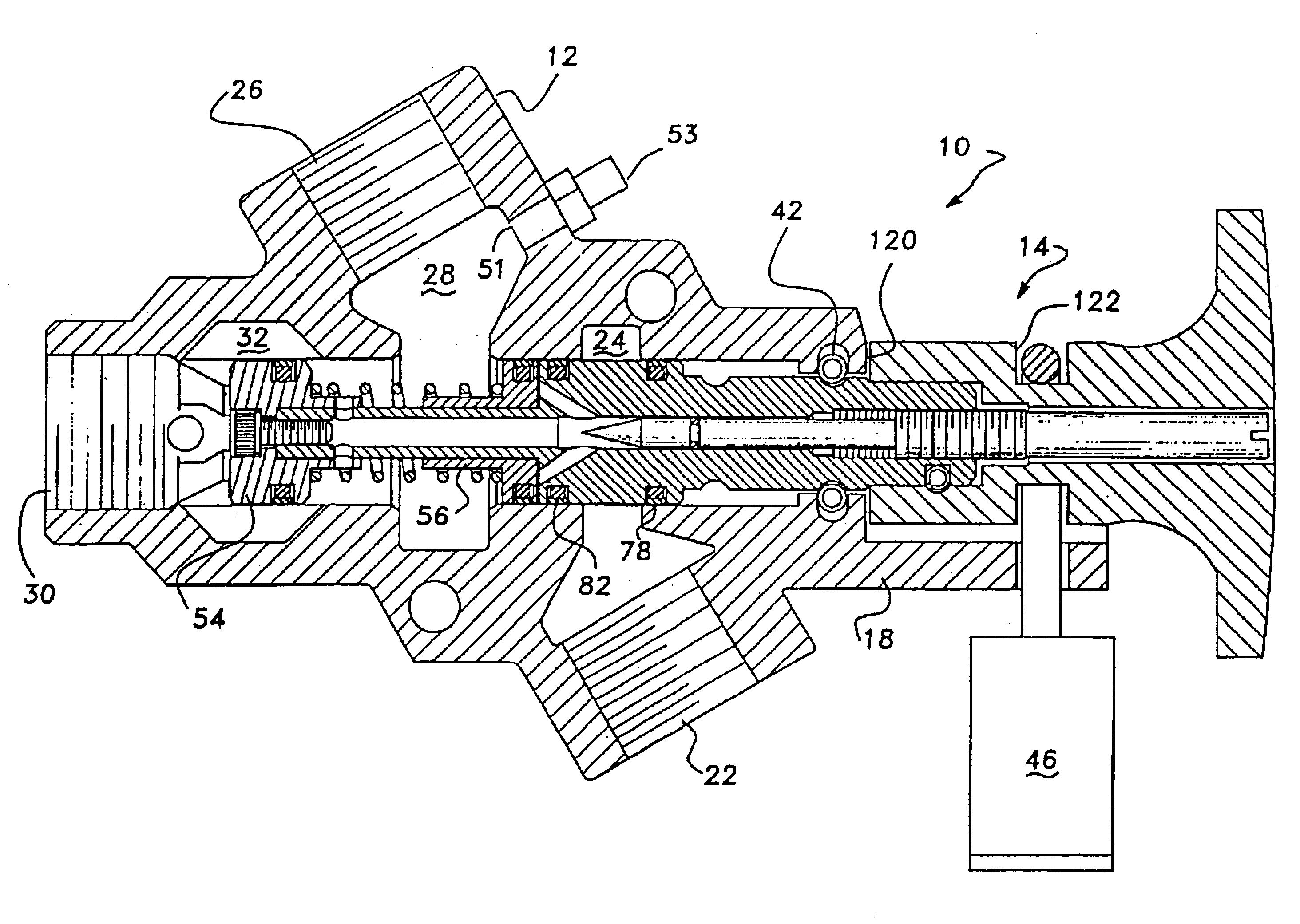
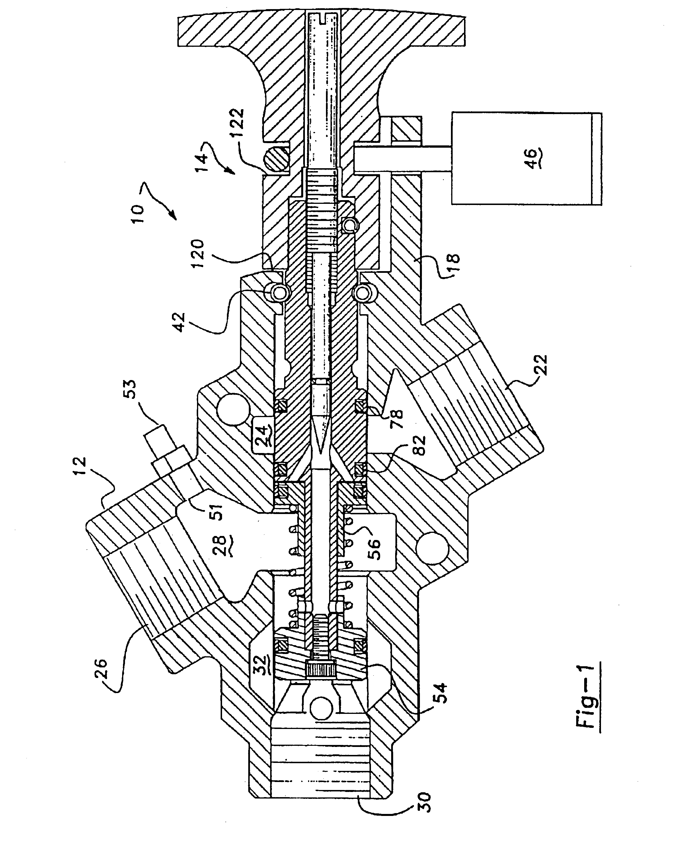
[0015]Referring now to the drawings in which like reference numerals designate like or corresponding parts throughout the several views, there is shown in FIG. 1 a fluid control valve incorporating a soft startup capability and pressure indicator system in accordance with the present invention, which is designated generally as reference numeral 10. Fluid control valve 10 comprises a valve housing 12 and a valve spool assembly 14.

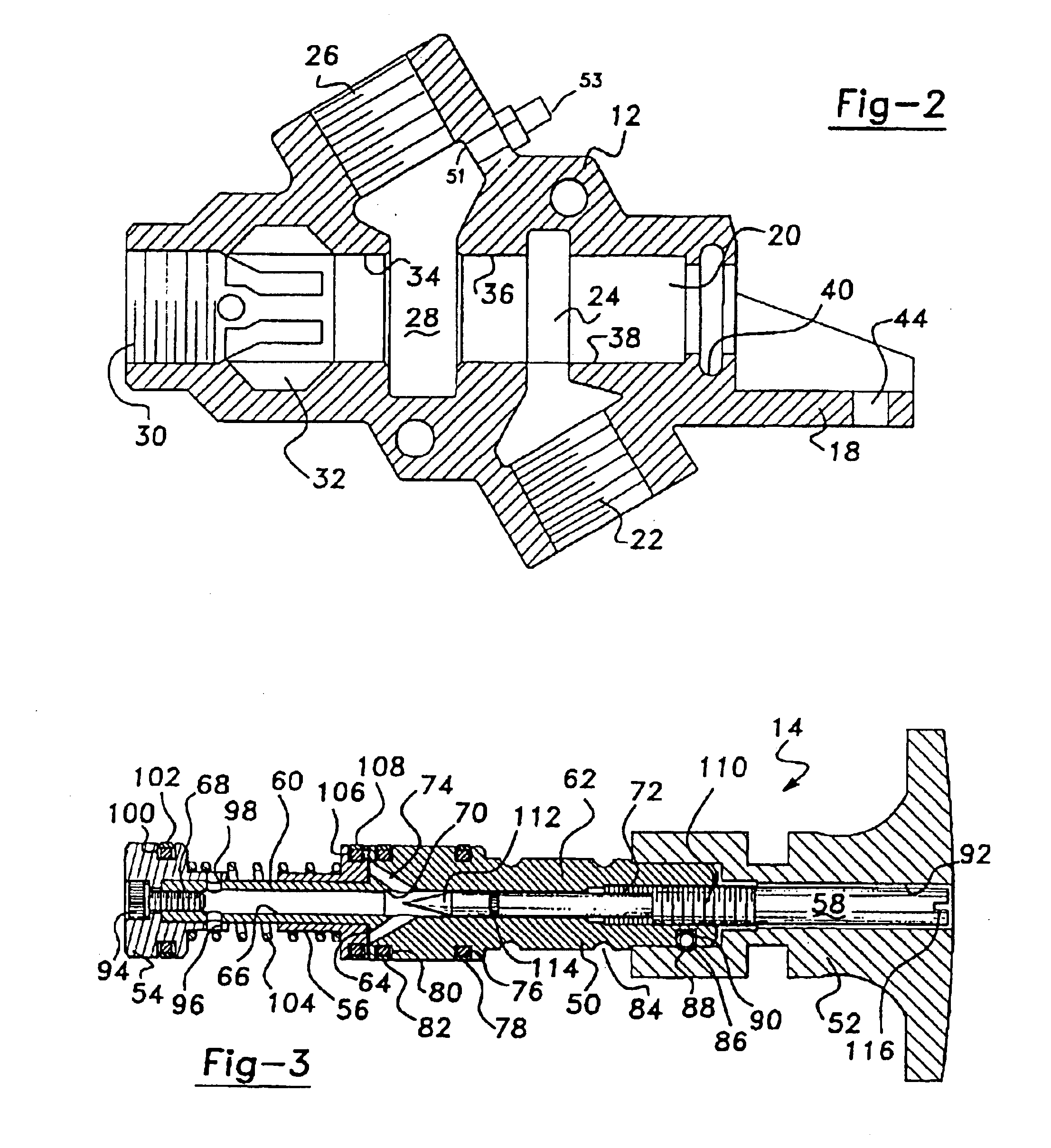
[0016]Referring now to FIGS. 1 and 2, valve housing 12 defines a locking flange 18 and a longitudinally extending bore 20 which communicates with an inlet port 22 through an inlet chamber 24, an outlet port 26 through an outlet chamber 28 and an exhaust port 30 through an exhaust chamber 32. Inlet port 22 is adapted to be connected to a source of compressed air, outlet port 26 is adapted to be co...


PUM


Abstract

A fluid control valve includes an adjustable soft start capability and pressure indicator device. The fluid control valve isolates an input port and connects an outlet port to an exhaust port when the fluid control valve is in its closed position. A system is provided for locking the fluid control valve in the closed position. The indicator device is used to provide an indication of the pressure within the outlet port to ensure safe operation.

Description

FIELD OF THE INVENTION[0001]The present invention generally relates to fluid control valves for use in pneumatic circuits and, more particularly, relates to safety shut-off valves for use in pneumatic circuits which provides a pressure indicator on the output to improve safety thereof.BACKGROUND OF THE INVENTION[0002]The manufacturing community utilizes air cylinders and other air actuated devices to control machinery, operate tools, and to perform various other manufacturing activities. These devices may be air actuated in a single direction with the return being accomplished by springs and / or gravity, or these devices may be air actuated in both directions with the control of the device being accomplished with an air valve. At certain times, the need arises to disconnect the supply of compressed air to the device. For example, one such time occurs when service or maintenance is required on the system incorporating air actuated devices. When disconnection of the supply of compresse...

Claims


Application Information

Patent Timeline
Patent Type & Authority Patents(United States)
IPC IPC(8): F16K37/00
CPCF16K37/0066Y10T137/7069Y10T137/8326Y10T137/86702Y10T137/87169
Inventor MADDEN, JEREMY S.SCHNELL, RICHARD E.
Owner ROSS OPERATING VALVE CO
Why Eureka
Try Eureka