End cap for roll tarp system

a roll tarp system and end cap technology, applied in the field of roll tarp systems, can solve the problems of tarping systems, difficult to form contoured end caps, and a tendency to collect transported materials under the plates, so as to reduce material requirements and component weight, easy to form, and add strength and resistance to bending

Inactive Publication Date: 2005-05-03
AERO INDS
View PDF18 Cites 26 Cited by
  • Summary
  • Abstract
  • Description
  • Claims
  • Application Information

AI Technical Summary

Benefits of technology

[0012]The end cap is preferably hollow in design to reduce material requirements and component weight. The front panel can include a number of stiffening indentations formed therein to add strength and resistance to bending, buckling and twisting.
[0013]In another feature of the invention, the end cap includes a deflection barrier formed at the underside of the end cap shell. The deflection barrier is configured to deflect material loaded into the container away from the end cap and into the body of the container. Preferably, the deflection barrier is a box-like structure so that it can be easily formed in a molding process. Moreover, the box-like structure adds strength and stiffness to the overall end cap. Stiffening indentations can be provided in the deflection barrier to provide further stiffness.

Problems solved by technology

One detriment with the end cap plates of these prior tarping systems is that transported material has a tendency to collect under the plates.
These contoured end caps can be even more problematic since they encompass a large volume and therefore provide more space for material to collect.
The material, such as grain or refuse, amassed beneath the end cap eventually degrades and can foul the end cap and even cause it to corrode.
Of course, damage to the end cap compromises its ability to support the tarp and maintain a tight seal against the elements.

Method used


Image

  • End cap for roll tarp system
  • End cap for roll tarp system
  • End cap for roll tarp system

Examples


Embodiment Construction

[0027]For the purposes of promoting an understanding of the principles of the invention, reference will now be made to the embodiment illustrated in the drawings and specific language will be used to describe the same. It will nevertheless be understood that no limitation of the scope of the invention is thereby intended. The invention includes any alterations and further modifications in the illustrated tools and further applications of the principles of the invention, which would normally occur to one skilled in the art to which the invention relates.

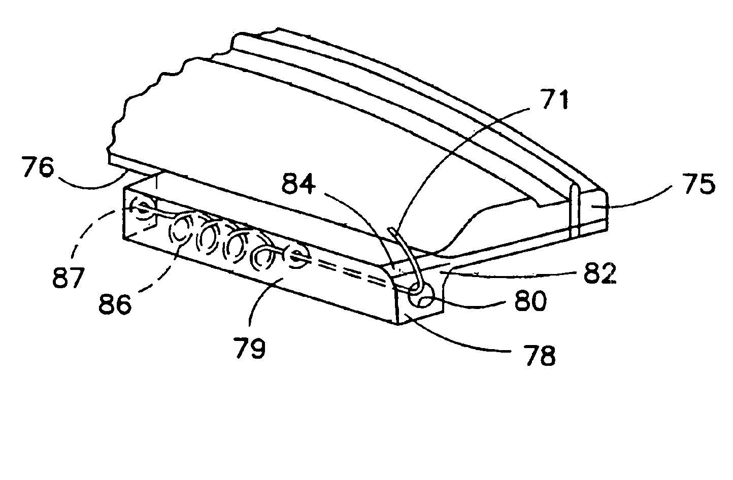
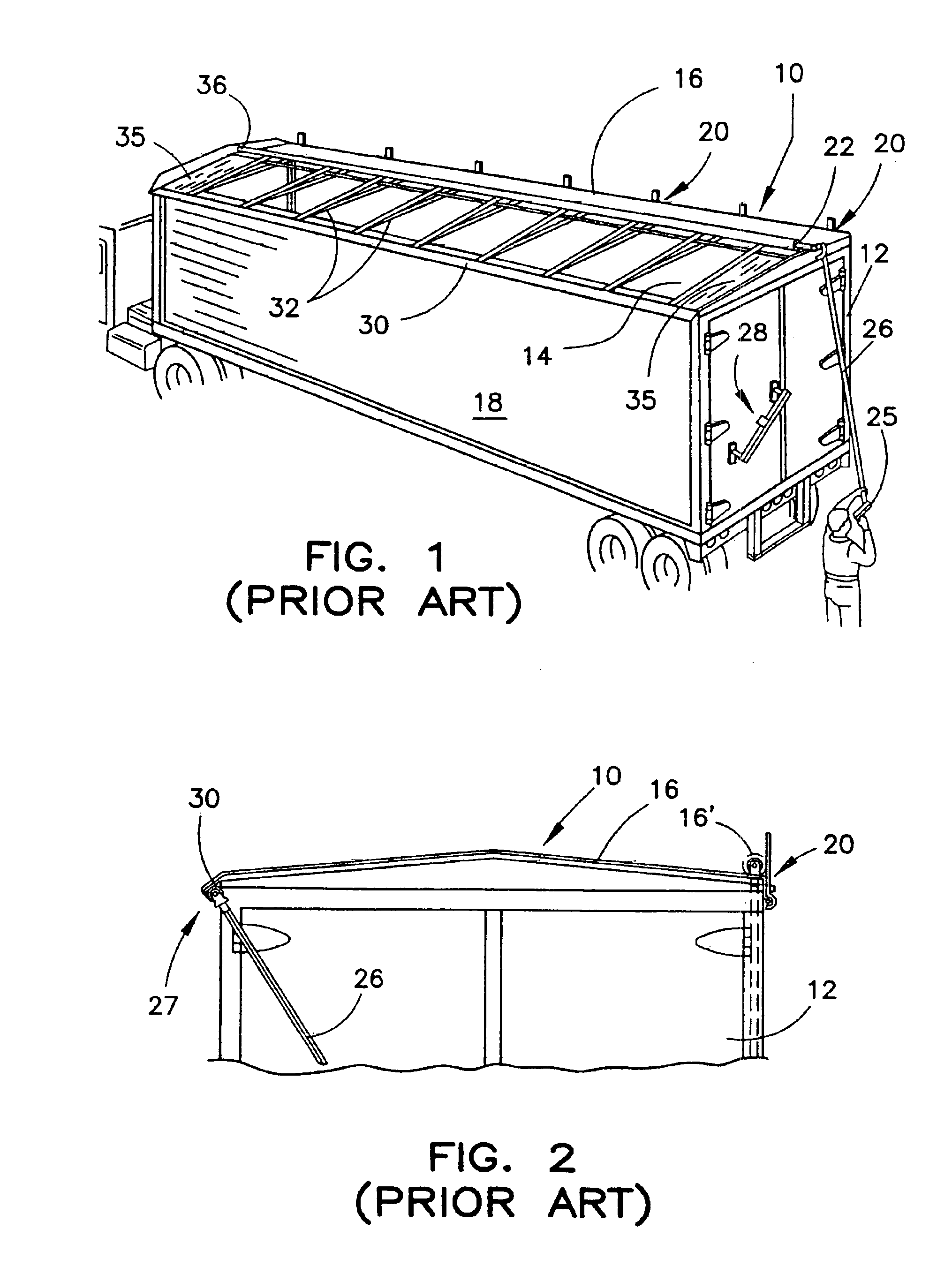
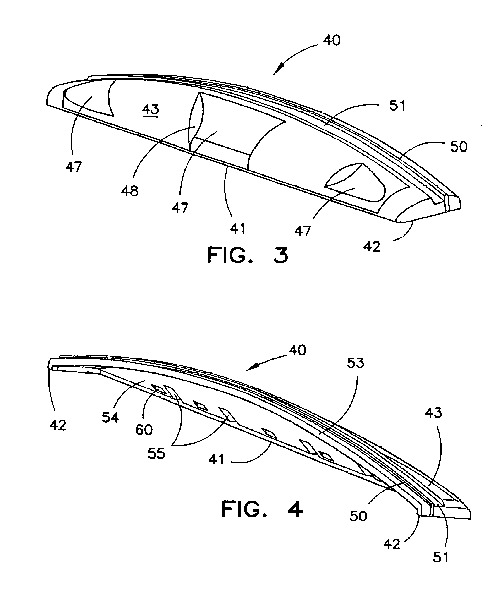
[0028]In accordance with the present invention, a novel end cap is provided for use with a roll tarping system, such as the system 10 illustrated in FIGS. 1 and 2. In particular, the inventive end cap can replace the end cap plates 35 depicted in FIG. 1. Thus, as shown in FIG. 3, an end cap 40 is provided that is of one-piece construction. Preferably, the end cap 40 is molded from a strong, durable plastic or fiberglass material that ...


PUM


Abstract

A one-piece molded end cap is provided for use with a container tarping system. The end cap is in the form of an aerodynamically shaped shell and includes a trough and ridge configuration at the rear edge to provide a sealing surface for the side edge of the flexible cover of the tarping system. A deflection barrier is formed at the underside of the end cap shell and is configured to deflect material loaded into the container away from the end cap. In a further embodiment, the end cap can include a tensioning mechanism integral with a front edge of the end cap. The tensioning mechanism includes an elongated body having a bore within which a tensioning element is disposed. The tensioning element applies tension to a drive mechanism of the tarping system through a cable.

Description

[0001]This application is a continuation of U.S. application Ser. No. 10 / 037,217, filed Nov. 9, 2001, which issued as U.S. Pat. No. 6,715,817 B2 on Apr. 6, 2004, which in turn claims the benefit of U.S. Provisional Patent Application U.S. 2003 / 0090124 A1, filed May 15, 2003.BACKGROUND OF THE INVENTION[0002]The present invention relates to tarping systems for open-topped containers, such as trailers on hauling vehicles. The invention pertains to improvements in roll tarp systems, and more particularly to end caps for use with such systems.[0003]Various types of truck, trailers and container bodies are designed to be loaded and unloaded through an open top. A typical application of such containers is to haul grain, earth or refuse. It is obviously desirable to provide the container with a covering, such as a flexible tarpaulin, to close the open top and prevent discharge of the materials housed therein during transit. The tarpaulins, or tarps, also serve to shelter the container conte...

Claims


Application Information

Patent Timeline
Patent Type & Authority Patents(United States)
IPC IPC(8): B60J7/08
CPCB60J7/085
Inventor NOLAN, ROBERTTUERK, JAMES R.
Owner AERO INDS
Why Eureka
Try Eureka