Vehicle bumper including a spoiler hinged between three positions of stable equilibrium

a technology of stable equilibrium and bumper, applied in the field of vehicles, can solve the problems that the requirements of the vehicle owner continue to become more difficult to pleas

Inactive Publication Date: 2005-05-03
CO PLASTIC OMNIUM
View PDF11 Cites 61 Cited by
  • Summary
  • Abstract
  • Description
  • Claims
  • Application Information

AI Technical Summary

Benefits of technology

[0009]The retracted position of the spoiler enables the ground clearance of the vehicle to be increased, thereby giving it greater ability to pass obstacles, in particular for off-road use.
[0012]This clutch mechanism, which is capable of allowing the spoiler to pass from its front position towards its rear position, and vice versa, can be actuated either manually, at will, or else automatically as a function of the conditions to which the vehicle is subjected. This provides great flexibility in use.
[0015]The bumper may further include an abutment which limits the upward stroke of the spoiler, said abutment being suitable for preventing the spoiler from passing from its high position towards its retracted position.

Problems solved by technology

Nevertheless, vehicle owner requirements continue to become more difficult to please.

Method used


Image

  • Vehicle bumper including a spoiler hinged between three positions of stable equilibrium
  • Vehicle bumper including a spoiler hinged between three positions of stable equilibrium
  • Vehicle bumper including a spoiler hinged between three positions of stable equilibrium

Examples


Embodiment Construction

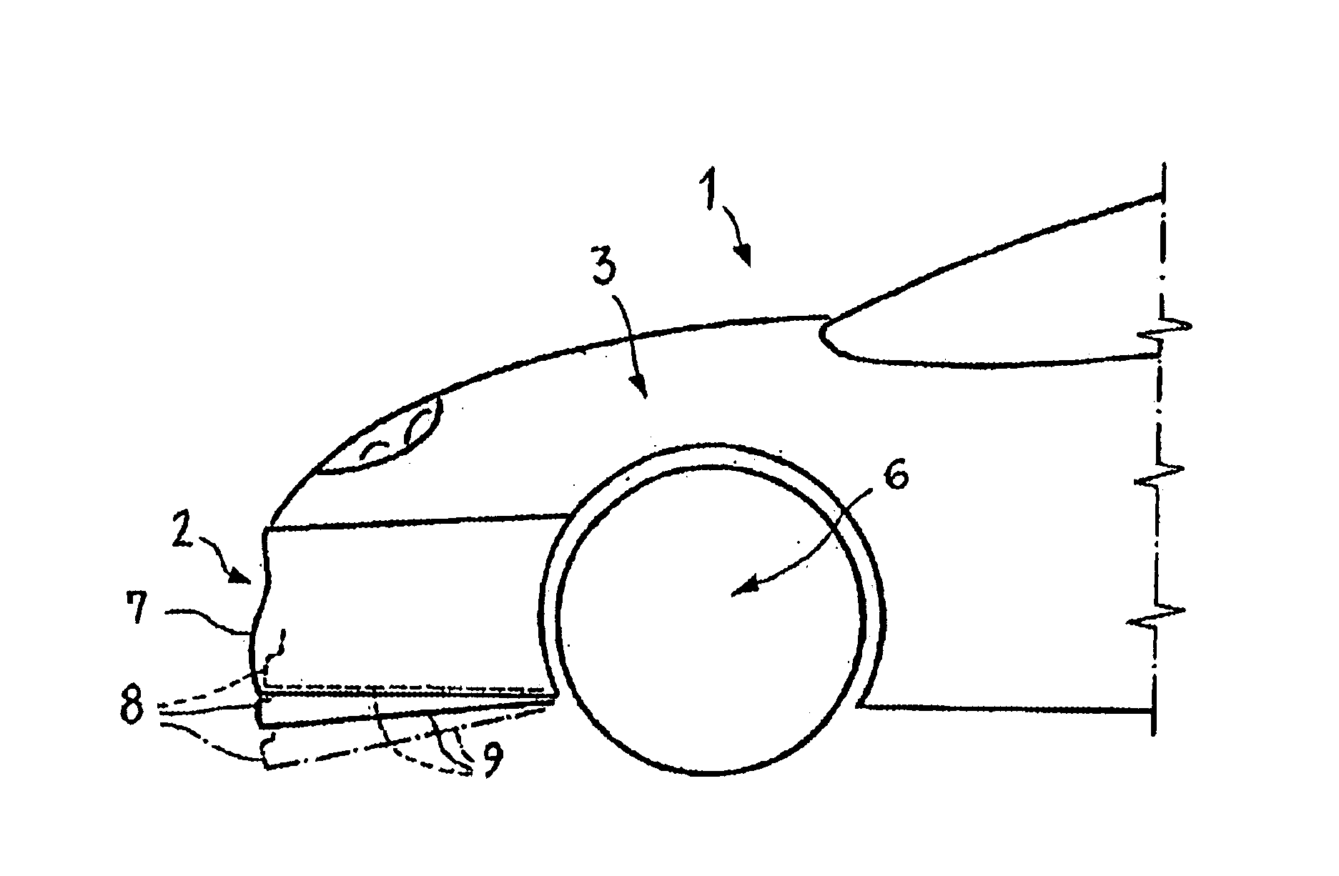
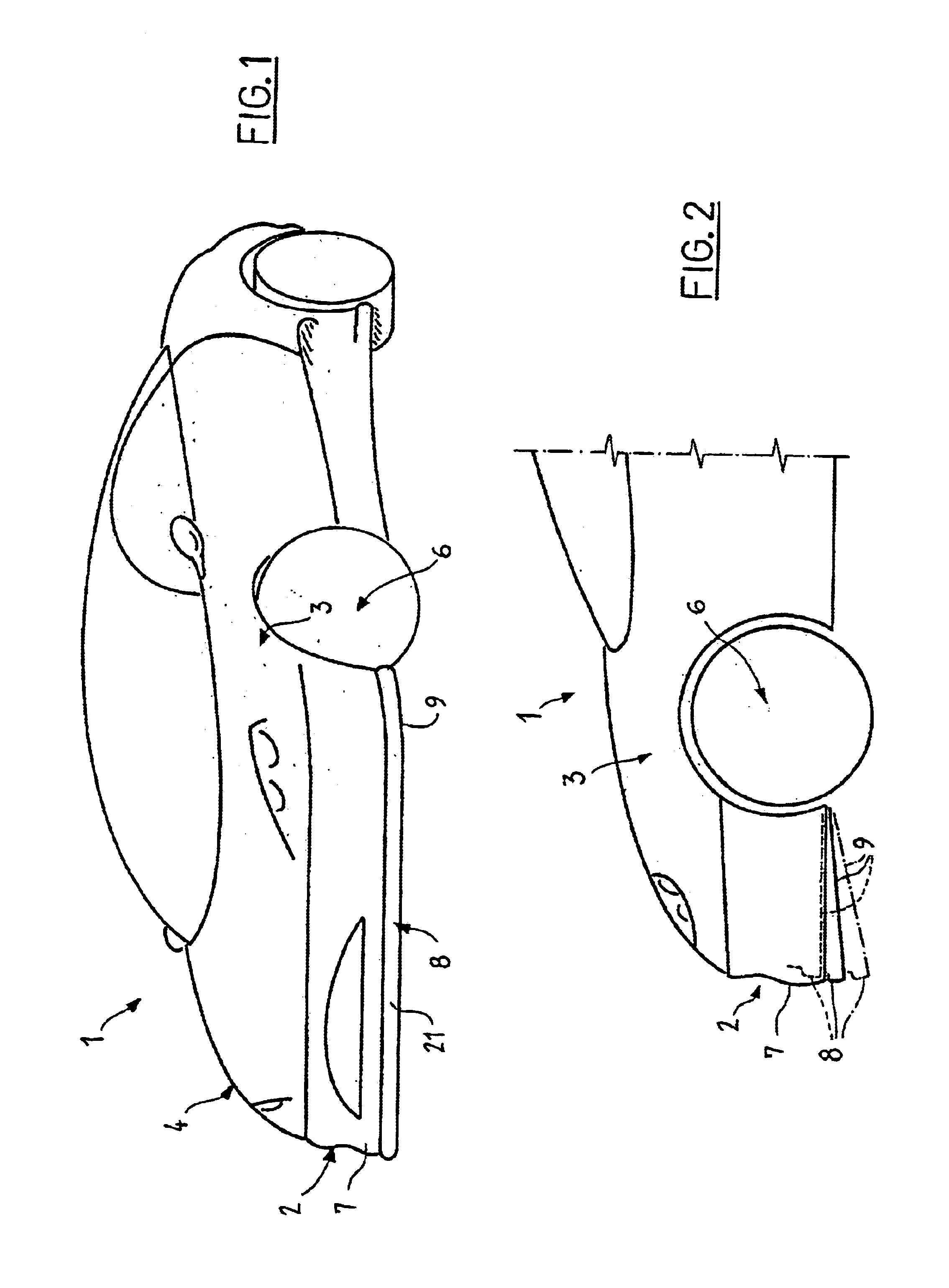
[0027]FIG. 1 shows a motor vehicle 1 fitted with a front bumper 2 which extends between the left front fender 3 and the right front fender 4 of the vehicle 1. Naturally, the shape proposed for the vehicle 1 is purely illustrative and cannot be considered limiting possible uses of the invention.

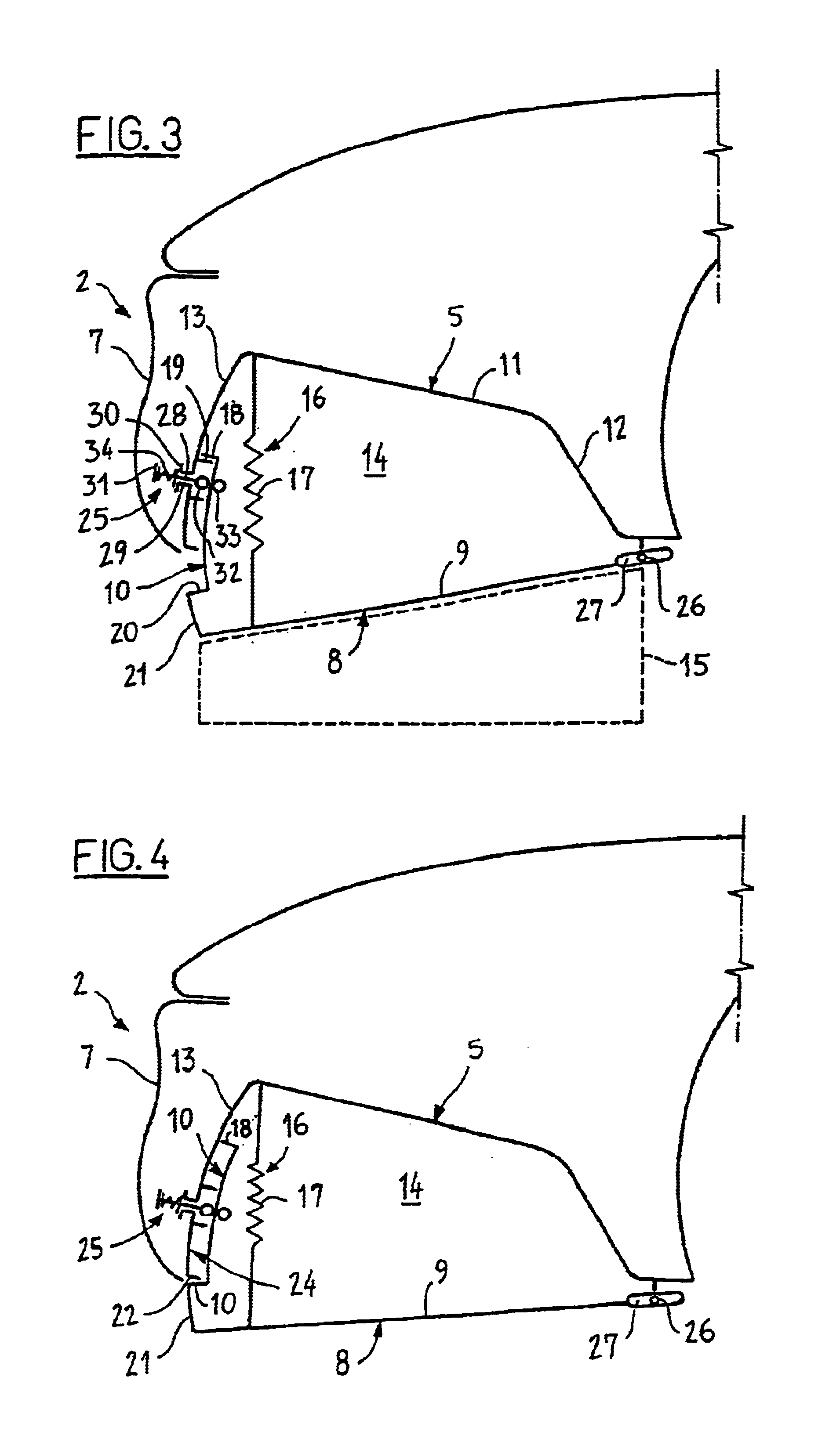
[0028]The bumper 2 comprises a spoiler support 5 situated in front of the front axle 6 of the vehicle 1, and fixed rigidly to or integral with the main structure of the vehicle. A shield 7 is mounted on the support 5. This shield 7, also referred to as a “bumper skin” performs an essentially decorative function, however in conventional manner it also serves to absorb impacts of small size.

[0029]The bumper 2 also comprises a spoiler 8 which is hinged to the support 5. The spoiler 8 serves firstly to improve the aerodynamics of the vehicle 1 at high speed by reducing its drag coefficient (Cx) and secondly, likewise at high speed, to improve the road holding of the vehicle 1 by creating a ground ...


PUM


Abstract

The invention relates to a motor vehicle bumper which comprises a shield and a spoiler hinged between two positions of stable equilibrium, namely a high position in which at least a part of the spoiler projects from the shield, and a low position in which the spoiler extends the bumper in a downward direction. The spoiler is suitable for adopting a third position of stable equilibrium, in which it is completely retracted behind the shield.

Description

[0001]The present invention relates to vehicle aerodynamics.[0002]It relates to a vehicle bumper which, for the purpose of modifying the aerodynamics of the vehicle as a function of its speed, includes a spoiler hinged between a high position, which it occupies at low speed, in order to facilitate traveling in built-up areas where it is necessary to be able to deal with the obstacles that are to be encountered therein (sidewalks, humps, sloping access ramps, etc.), and a low position, which it occupies at high speed, in order to reduce the value of the vehicle's drag coefficient (usually written Cx), thereby providing substantial savings in fuel consumption while also increasing the ground effect to improve the vehicle's road holding.BACKGROUND OF THE INVENTION[0003]Such a bumper is known in particular from the French patent application in the name of the Applicant published under the No. FR-2 795 039.[0004]That bumper, which is already fitted to a certain number of vehicles on the ...

Claims


Application Information

Patent Timeline
Patent Type & Authority Patents(United States)
IPC IPC(8): B62D35/00
CPCB62D35/005Y10S180/903Y02T10/82
Inventor JACQUEMARD, CLAUDEFAYT, ARNOLD
Owner CO PLASTIC OMNIUM
Why Eureka
Try Eureka