Positive-displacement rotary pump

a rotary pump and displacement technology, applied in the direction of rotary or oscillating piston engines, intermeshing engagement engines, rotary piston engines, etc., can solve the problems of noise of the pump itself, noise of the operation, and rapid decline of the efficiency of the pump of this typ

Inactive Publication Date: 2005-05-03
MORSELLI MARIO ANTONIO
View PDF18 Cites 29 Cited by
  • Summary
  • Abstract
  • Description
  • Claims
  • Application Information

AI Technical Summary

Benefits of technology

[0010]One advantage of the present invention consists in that the axial position of the rotors is unambiguously defined even in the event that they are subjected to axial loads or pressures owing to mechanical contact with the shell or portions thereof. In fact, it is known that, in the running-in stages of pumps of known type, it is accepted and desirable for there to be contact of portions of the rotors with the shell so that the rotors remove an extremely small layer of material until an individual seat has been “scooped out”, in such a manner that, when the pump is used after the running-in operation, the clearance between the teeth of the rotors and the shell has minimal dimensions. This slight interference between the helical teeth of the rotors and the shell of the pump produces additional axial loads on the rotors, which mainly have an unknown value. The present invention, by providing a fixed plane of reference, also ensures the correct positioning of the rotors in the initial running-in stage of the pump, and even in the event of interference between the rotors and the shell, when unknown axial forces resulting from the above-mentioned mechanical contact are added to the axial forces expected in normal operation of the pump.

Problems solved by technology

In fact, the efficiency of pumps of this type declines rapidly if the leak-tightness is not total.
Another problem which the manufacturers of pumps have to deal with is the noise of the pumps themselves, owing to irregular phenomena, or “ripples”, in the transfer of the fluid.
The above-mentioned solutions of the prior art have the common problem consisting in the noise of operation caused by the instantaneous oscillations of the output over time, better known as ripple noise.
The noise produced can reach levels which are also unpredictable where the above-mentioned members begin to resonate with the frequency of oscillation or ripple.
This variation determines oscillations in the axial loads on the bushings, which contributes to an increase in the noise of the pump, besides reducing the total efficiency thereof.
This oscillation of the axial loads, which is normally of small magnitude in gear pumps having straight teeth, becomes significantly greater in gear pumps having helical teeth, in which the meshing between the gears is the cause of both mechanical and hydraulic axial loads such that the balance and the taking-up of clearances on the bushings illustrated in FIGS. 1 and 2 is not completely satisfactory, since the hydraulic axial loads have perceptible pulses.

Method used


Image

  • Positive-displacement rotary pump
  • Positive-displacement rotary pump
  • Positive-displacement rotary pump

Examples


Embodiment Construction

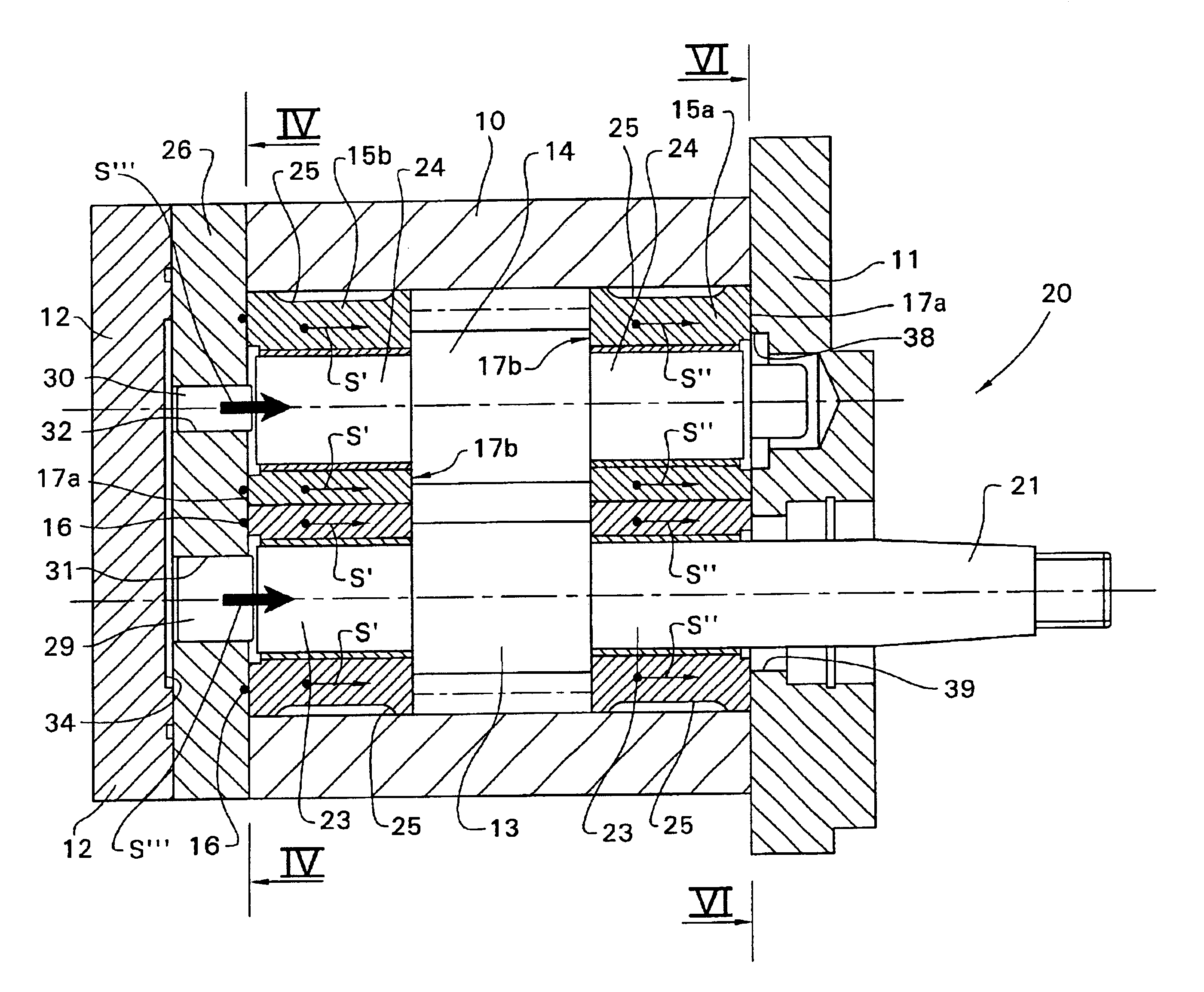
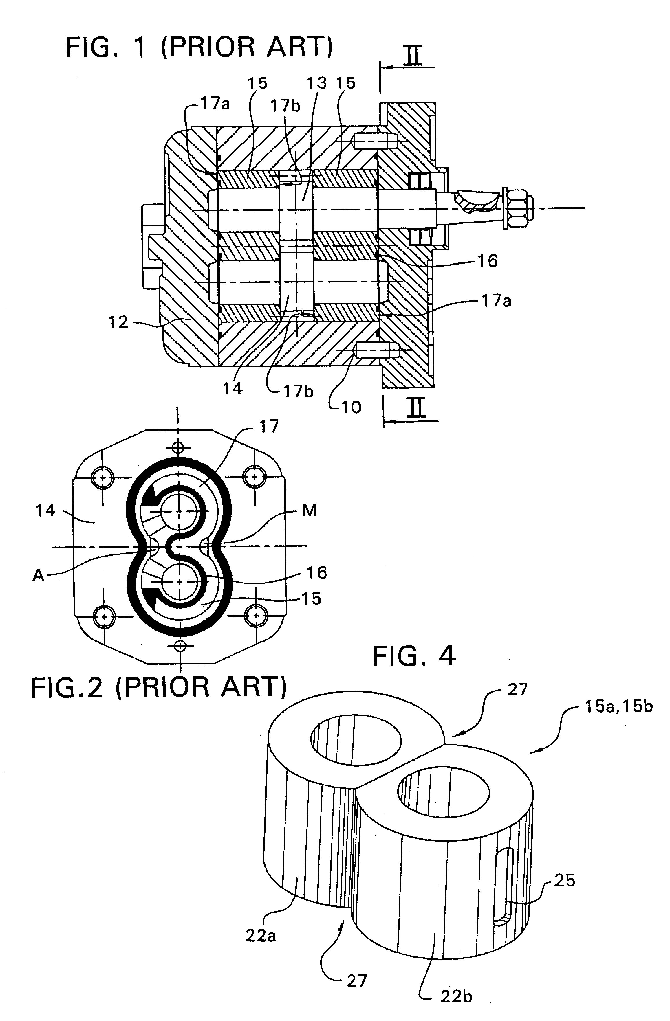
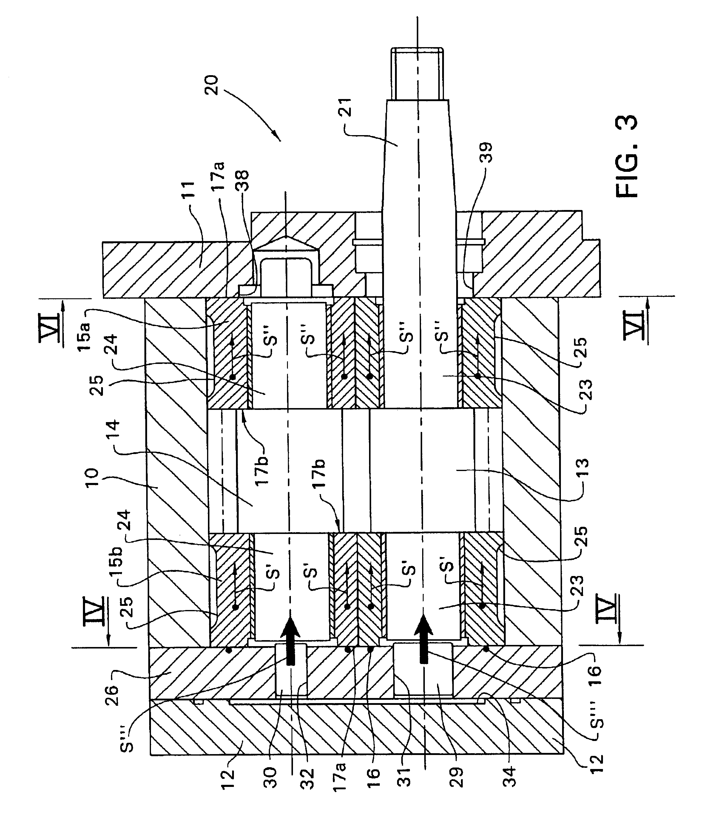
[0019]Now with reference to FIG. 3, a gear pump 20 comprises, as already described above with reference to the known pump in FIGS. 1 and 2, a shell 10 having an output opening and an intake opening for a fluid, inside which are housed the driving gear 13 and the driven gear 14. In the example in the Figure, the gears 13 and 14 are of the cylindrical type having helical teeth, but naturally the invention can also be used with different gears, for example, a pair of straight spur gears, similar to that in the prior art illustrated in FIG. 1.

[0020]The shell 10 is closed at the two ends by the front cover 11 and the rear cover 12. The end 21 of the shaft 23 of the driving gear 13 protrudes from the front cover 11. For ease of illustration, the seals between the shaft 23 and the front cover 11 have been omitted in FIG. 3. Inside the shell 10, the shafts 23 and 24 of the gears 13 and 14, respectively, are supported by two bushing sets, a front bushing set 15a and rear bushing set 15b. Eac...


PUM


Abstract

A positive-displacement rotary pump comprising a pair of meshing gears (13, 14) or rotors, consisting of a driving gear and a driven gear, contained in a shell (10) having an output opening and an intake opening for a fluid. The gears (13, 14) include shafts (23, 24) which are supported by bushings (15a, 15b) having two faces (17a, 17b) which are subjected, in use, to pressures which bring about an axial load on the bushing itself, wherein the resultant of the axial loads (S′, S″) on the two bushings has a predetermined direction so as to move the bushings (15a, 15b) and the gears (13, 14) as a whole into close abutment with a predetermined reference plane (VI—VI).

Description

FIELD OF THE INVENTION[0001]The present invention relates to positive-displacement rotary pumps and specifically gear pumps.BACKGROUND OF THE INVENTION[0002]Gear pumps generally comprise two gears, one of which, known as the driving gear, is connected to a drive shaft and causes the other wheel, known as the driven gear, to rotate. The pumps of this type for high pressures are generally produced with a so-called “balanced” or “equilibrated” configuration, in which the two opposing faces of the bushings for supporting the gears are subjected to pressures over areas which, although they are large in absolute terms, are not very different from each other in order to generate a moderate differential force which tends to keep each bushing in contact with the gears.[0003]FIGS. 1 and 2 illustrate an example of a gear pump of known type. In particular, FIG. 1 is a longitudinal section along a plane which extends through the axes of rotation of the two gears, and FIG. 2 is a section taken on...

Claims


Application Information

Patent Timeline
Patent Type & Authority Patents(United States)
IPC IPC(8): F04C15/00F04C2/00F04C2/14
CPCF04C15/0042F04C15/0026F04C2/14
Inventor MORSELLI, MARIO ANTONIO
Owner MORSELLI MARIO ANTONIO
Why Eureka
Try Eureka