Firing simulator

a simulator and firing technology, applied in the field of firing simulators, can solve the problems of complex target arrangement, high cost, and often unwieldy methods

Inactive Publication Date: 2005-05-03
SAAB AB
View PDF26 Cites 25 Cited by
  • Summary
  • Abstract
  • Description
  • Claims
  • Application Information

AI Technical Summary

Problems solved by technology

This method is often unwieldy and takes a great deal of time, since the method is iterative.
Arrangement of the target thus becomes complex and expensive, which means that the number of adjustment devices per trainee in a unit must be limited during firing training using weapons by means of the use of a simulator.
This means that the trainees must queue in order to carry out the adjustment, and considerable time must be allocated for preparing for the training, losing valuable training time.
It is clear that this device also is complex and expensive, and even if the alignment procedure is more rapid, a problem arises also here with the formation of queues that tends to require a long time in preparation for the training, since the method according to the said documents is still based on observation of the results of firing the simulator in a target system.

Method used


Image

  • Firing simulator
  • Firing simulator
  • Firing simulator

Examples


Embodiment Construction

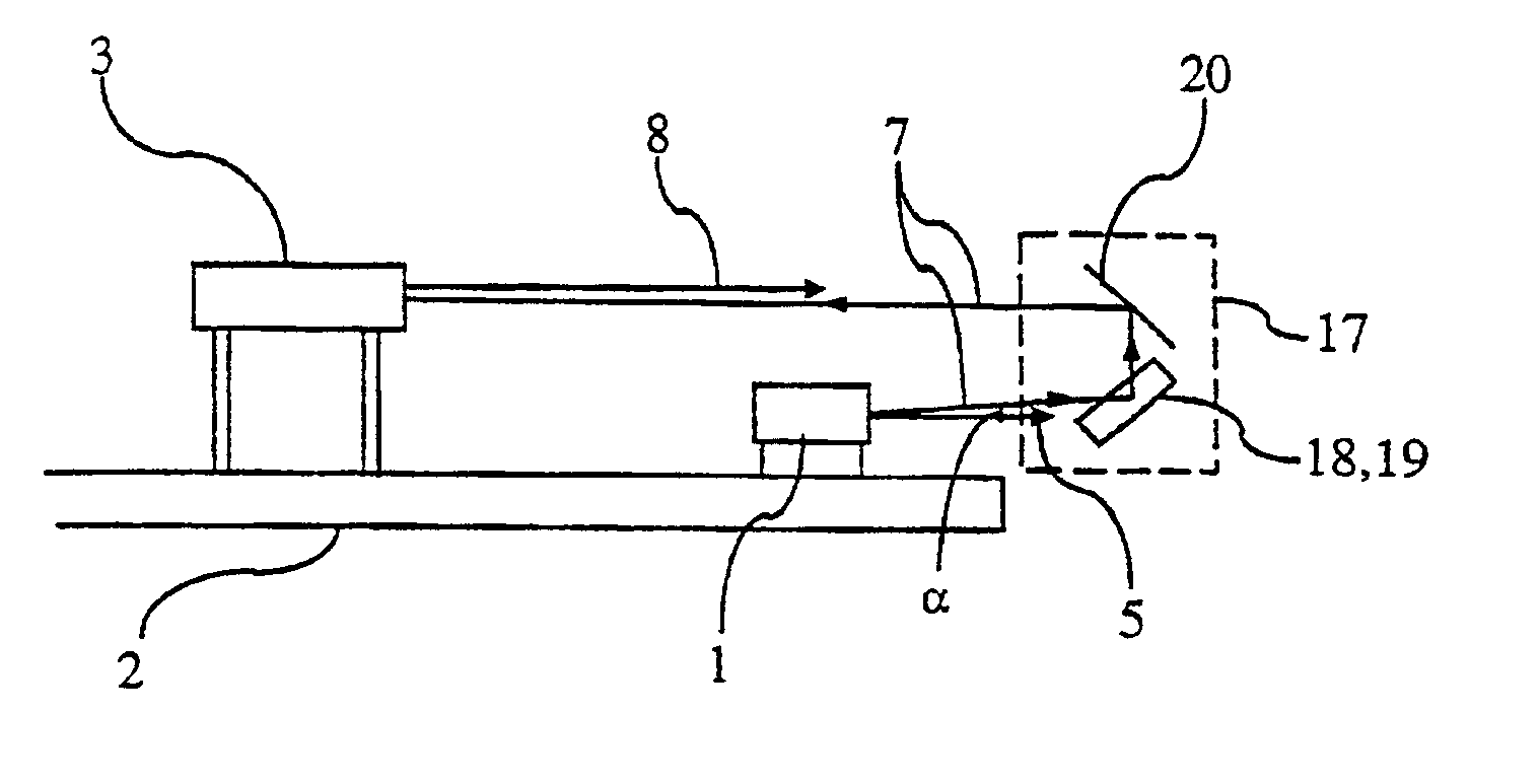
[0008]A device and a method for the simulation of firing by means of a weapon are described according to the aspect of the invention. This is carried out with a simulator, mounted on a weapon with a sight, with the simulator arranged to emit an electromagnetic simulator beam exiting along a simulator axis. Furthermore, the simulator is arranged to emit a visible alignment beam along an alignment axis, which forms a fixed and known angle with the aforementioned simulator axis.

[0009]The term “axis” is here used to describe the axis of symmetry of the directions of propagation of the respective beams.

[0010]The simulator contains a means of adjustment to collectively control both of the aforementioned axes, the simulator axis and the alignment axis, so that they maintain their fixed and known relative angular relationship during the adjustment.

[0011]The alignment beam is made visible in the weapon's sight by means of a reflection device.

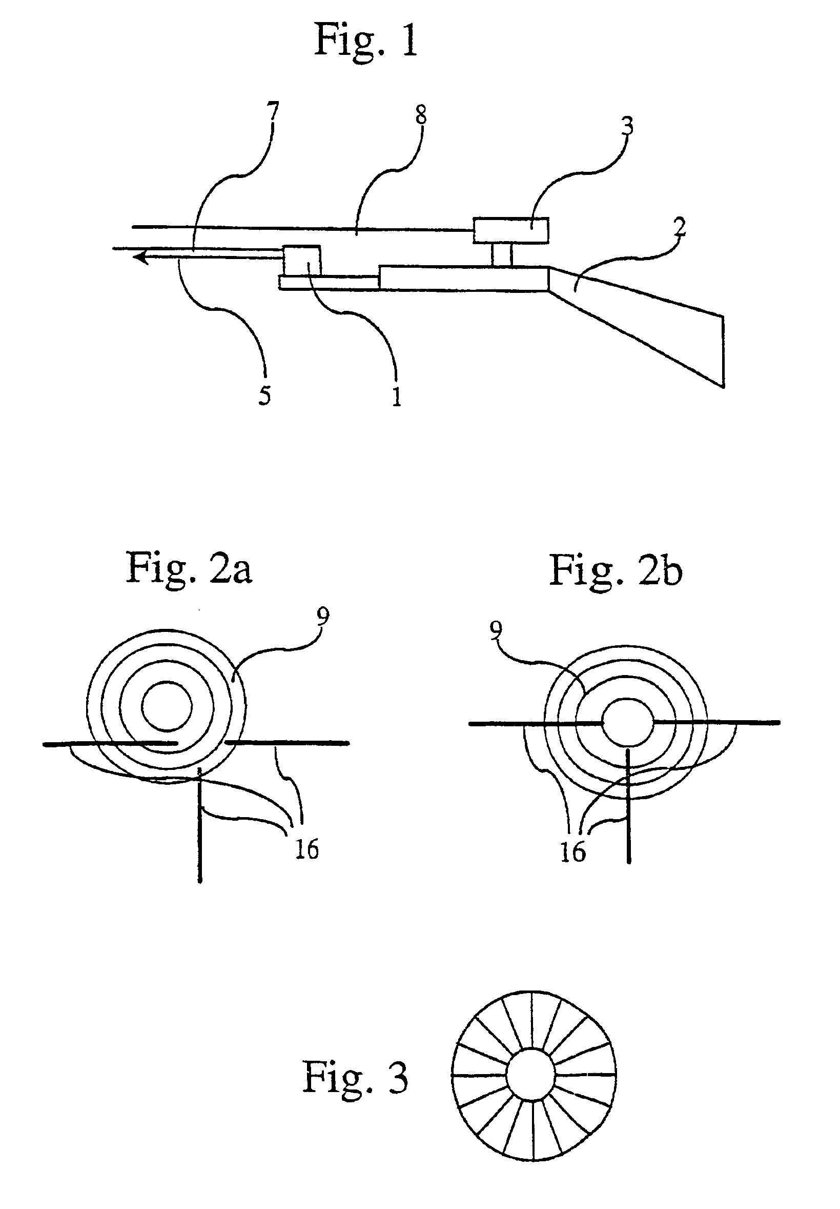
[0012]The alignment beam can generate a guide mark...


PUM


Abstract

An alignment device for alignment of a weapon and a weapon simulator mounted on the weapon. The weapon is provided with a sight and the weapon simulator is equipped with a first device arranged to emit an electromagnetic simulator beam exiting along a simulator axis. The alignment apparatus includes a second device arranged to generate an alignment beam along an alignment axis. The angle between the simulator axis and the alignment axis is fixed and known. A reflection device is arranged to reflect the alignment beam into the sight. An adjuster is arranged to collectively guide the alignment axis and the simulator axis during the alignment of the simulator axis with the sight so that the axes during the alignment maintain the fixed relative angular relationship.

Description

TECHNICAL AREA[0001]The invention concerns a simulator for simulating firing. The simulator is intended for mounting onto a weapon with a sight.THE PRIOR ART[0002]During simulated firing, the simulator emits a laser beam or a beam of electromagnetic radiation that has been generated by another technique than using a laser. The radiation can be detected by one or several detectors belonging to a target system mounted on the target. The emitted radiation, for example laser radiation, has different intensities in different directions of radiation, whereby these are collectively termed the laser lobe. If the radiant intensity from the laser lobe at a particular distance from the emitter and in a particular direction exceeds a detection level at any detector on the target, a simulated effect of firing with the weapon towards the target system that lies in the said direction and at the said distance is obtained.[0003]When a simulator is attached to a weapon, the direction of fire of the s...

Claims


Application Information

Patent Timeline
Patent Type & Authority Patents(United States)
IPC IPC(8): F41G3/26F41G3/00F41G3/32F41A33/02F41G1/54
CPCF41A33/02F41G1/545F41G3/32F41G3/2655F41G3/265
Inventor ROBERTSSON, HANSFREDRIKSSON, ARNOLD
Owner SAAB AB
Why Eureka
Try Eureka