
Dust extraction shroud for a power tool

a technology for power tools and dust extraction shrouds, which is applied in ventilation systems, portable drilling machines, domestic stoves or ranges, etc., can solve the problems of reducing the effectiveness of dust extraction machines and the dust extraction system suffers, and achieves the effect of reducing the weight and physical dimensions of dust extraction machines

Inactive Publication Date: 2005-05-03
BLACK & DECKER INC
View PDF70 Cites 59 Cited by
  • Summary
  • Abstract
  • Description
  • Claims
  • Application Information

AI Technical Summary

Benefits of technology

[0011]By providing a shroud with at least one second inlet (i.e. air inlet) arranged remotely from the surface being drilled, this provides the advantage that it is more difficult for the or each second inlet to become blocked with dust. This also provides the advantage that as the or each second inlet is defined between the corresponding protruding portion and the adjacent part of the body portion, the or each second inlet can be made larger than in the prior art.
[0026]The apparatus may further comprising timer means for deactivating said apparatus a predetermined time after deactivation of the power tool. This provides the advantage that dust produced even after the tool is deactivated is removed.

Problems solved by technology

Such drilling work typically involves releasing large amounts of dust.
This prior art dust extraction system suffers from the drawback that the air inlets for the vacuum source are disposed very near to, or on the surface being drilled.
As a result of this, the inlets can become easily blocked thereby reducing the effectiveness of the dust extractor.

Method used


Image

  • Dust extraction shroud for a power tool
  • Dust extraction shroud for a power tool
  • Dust extraction shroud for a power tool

Examples


Embodiment Construction

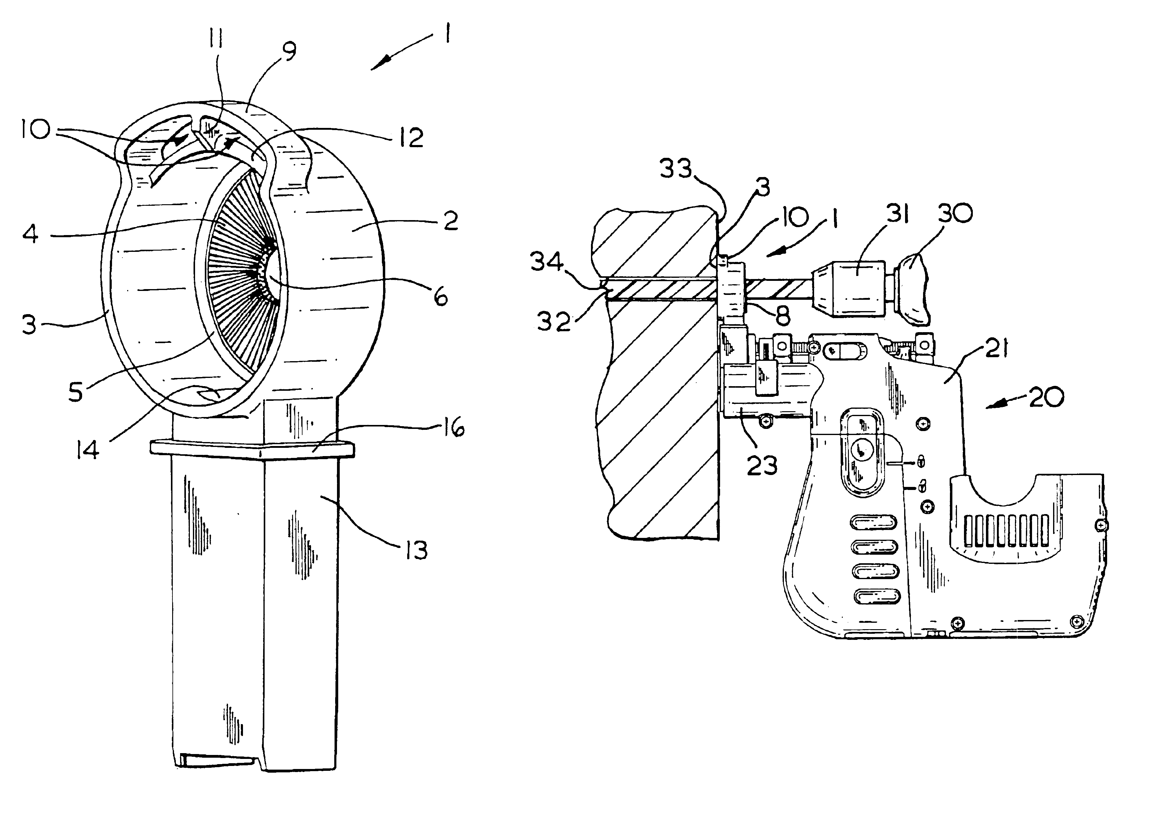
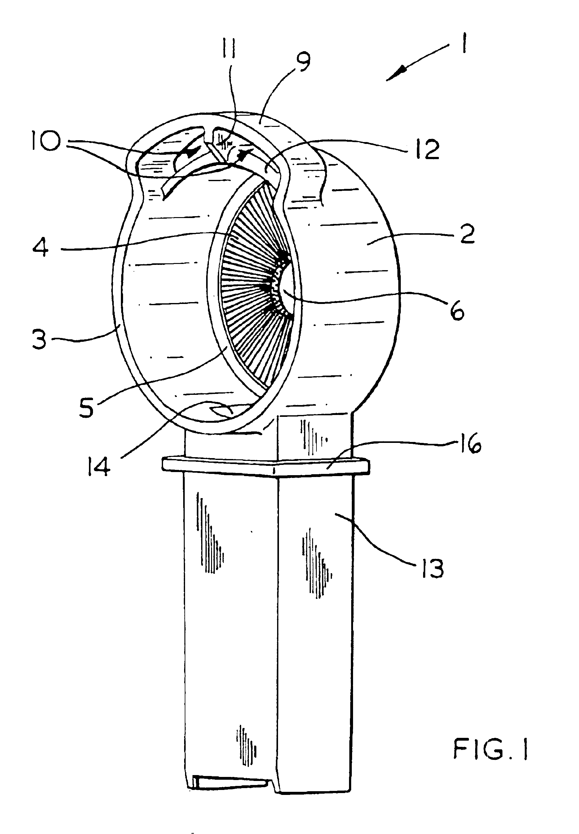
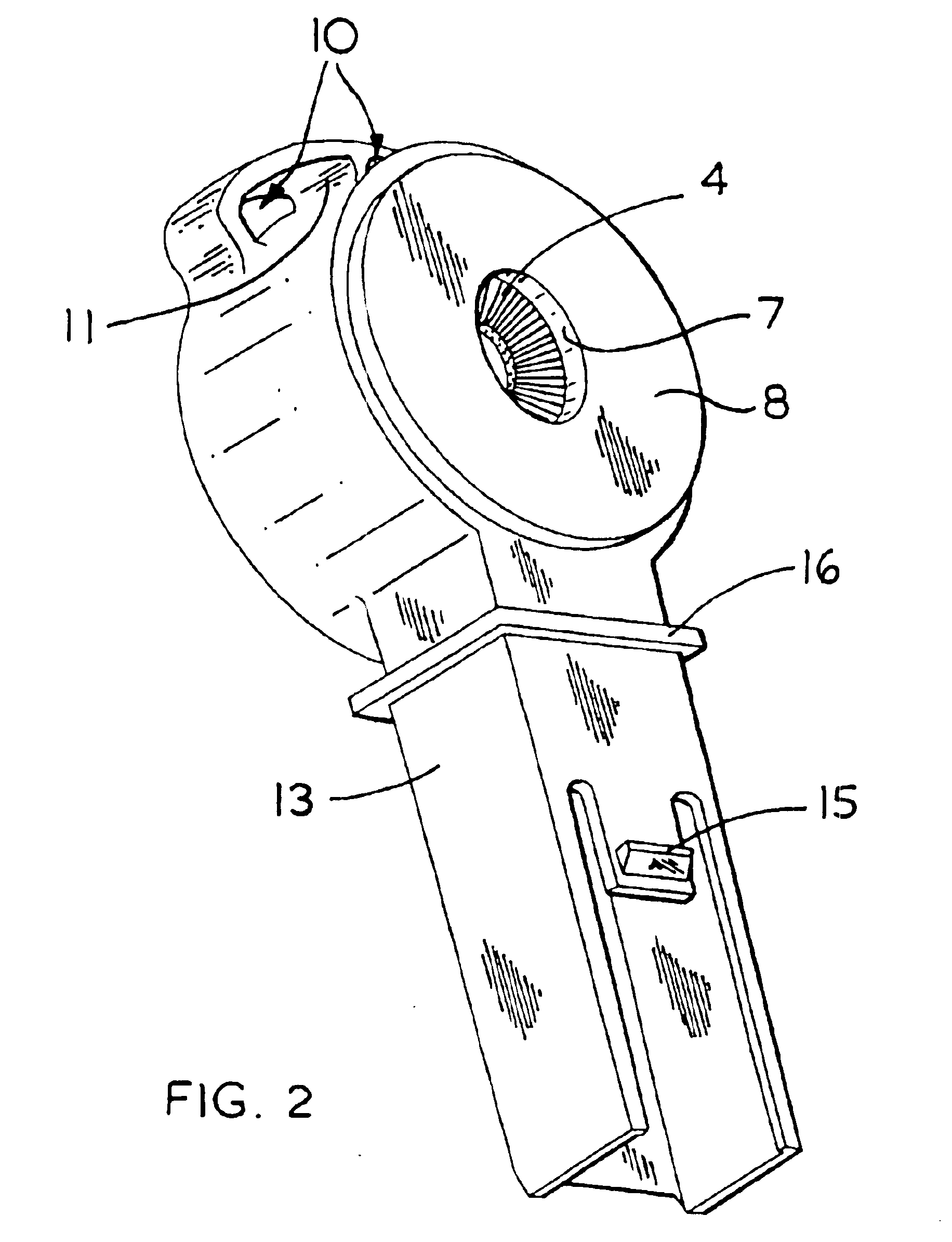
[0047]Referring to FIGS. 1 to 4, a dust extraction shroud 1 is formed from moulded plastic material and has a body portion 2 of substantially circular cross-section. The body portion 2 has a rim 3 adapted to be placed against a wall or other structure to be drilled. Rim 3 defines a first inlet and is substantially flat such that when placed against a wall there is little or no space between the wall and the edges of the inlet.

[0048]A circular brush 4 is disposed on the opposite side of body portion 2 to the rim 3, the bristles of brush 4 extending radially inwardly from a circular rim 5 and end at a point short of the central axis of body portion 2, such that a circular gap 6 defining a third inlet is left in the centre of the brush 4.

[0049]A circular aperture 7 is provided on rear face 8 of body portion 2, the aperture 7 being larger than the circular gap 6 in the brush 4. This feature is best shown in FIGS. 2 and 3. A drill bit (not shown) of a hammer drill, the drill bit having a...


PUM

PropertyMeasurementUnit
electrical poweraaaaaaaaaa
timeaaaaaaaaaa
suctionaaaaaaaaaa

Abstract

A dust extraction shroud for a drill, which surrounds a drill bit and which lies adjacent the work surface, comprises a body portion defining a first inlet adapted to engage the work surface and to surround the location at which said bit penetrates the surface. The shroud body further defines a first outlet connected to a source of suction and a third inlet for allowing the bit to pass through said body portion. A first sealing means is arranged in said third inlet for surrounding said bit and resisting the flow of air. Wherein said body portion includes at least one protruding portion defining a second inlet between said protruding portion and an adjacent part of said body, and on a side of said protruding portion remote from the first inlet. The second inlet admits air to enter said body portion and travel to the first outlet.

Description

[0001]The present invention relates to a dust extraction shroud for a power tool, and to a dust extraction apparatus incorporating such a shroud. The invention relates particularly, but not exclusively, to a dust extraction shroud for a hammer drill.BACKGROUND OF THE INVENTION[0002]Many types of building work involve drilling into and / or demolishing walls and concrete structures, with hand held tools such as drills and combined hammer drills. Such drilling work typically involves releasing large amounts of dust. German Patent Application DE4038941 describes a dust extraction system for a portable power drill in which the drill bit passes into a shroud held flush against the wall or structure being drilled. The shroud is connected to a source of suction which removes dust from the shroud as it is being produced.[0003]This prior art dust extraction system suffers from the drawback that the air inlets for the vacuum source are disposed very near to, or on the surface being drilled. As ...

Claims


Application Information

Patent Timeline
Patent Type & Authority Patents(United States)
IPC IPC(8): B23Q11/00
CPCB23Q11/0046Y10T408/50
Inventor STAAS, ERNSTARICH, KLAUS-DIETERHERTING, RAINERBERNHART, RALF
Owner BLACK & DECKER INC
Learn More