Transfer for a four-wheel drive vehicle

a technology for four-wheel drive vehicles and transmission arrangements, applied in mechanical devices, transportation and packaging, gearing, etc., can solve problems such as inconveniences

Inactive Publication Date: 2005-05-03
SUZUKI MOTOR CORP
View PDF12 Cites 9 Cited by
  • Summary
  • Abstract
  • Description
  • Claims
  • Application Information

AI Technical Summary

Problems solved by technology

In a conventional transfer arrangement for the four-wheel drive vehicle, e.g., the transfer for a part-time four-wheel drive (referred to as “4WD”) vehicle equipped with a switching system between “high” and “low” ranges, there are inconveniences described below when the system is equipped with the center differential to provide a full-time four-wheel drive position.

Method used


Image

  • Transfer for a four-wheel drive vehicle
  • Transfer for a four-wheel drive vehicle
  • Transfer for a four-wheel drive vehicle

Examples


Embodiment Construction

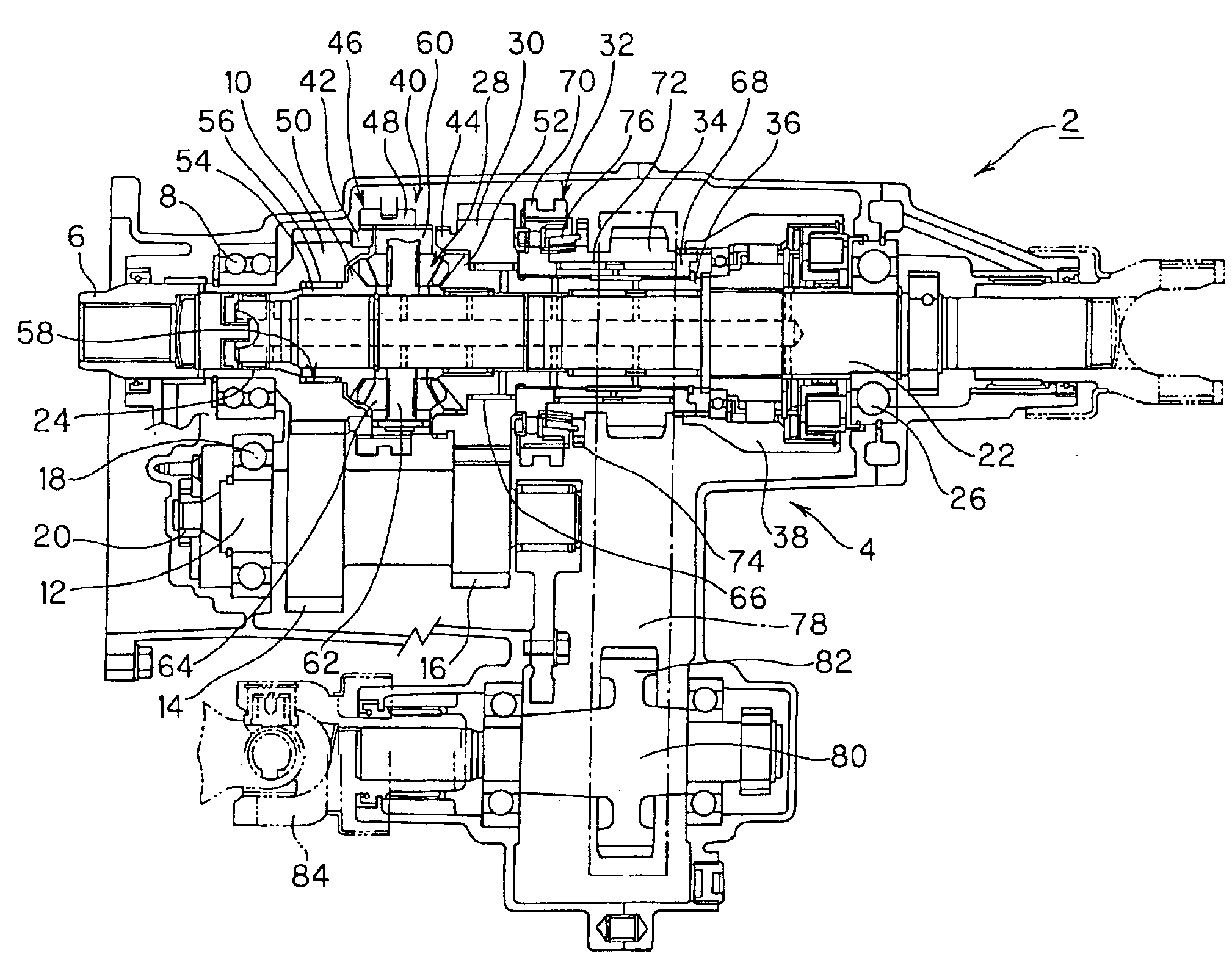
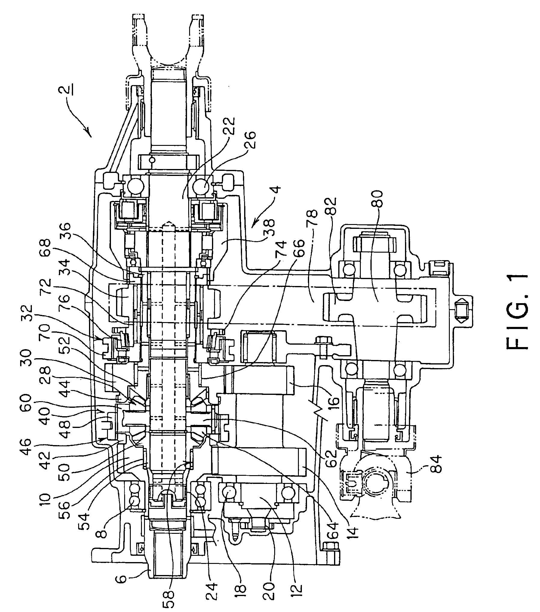
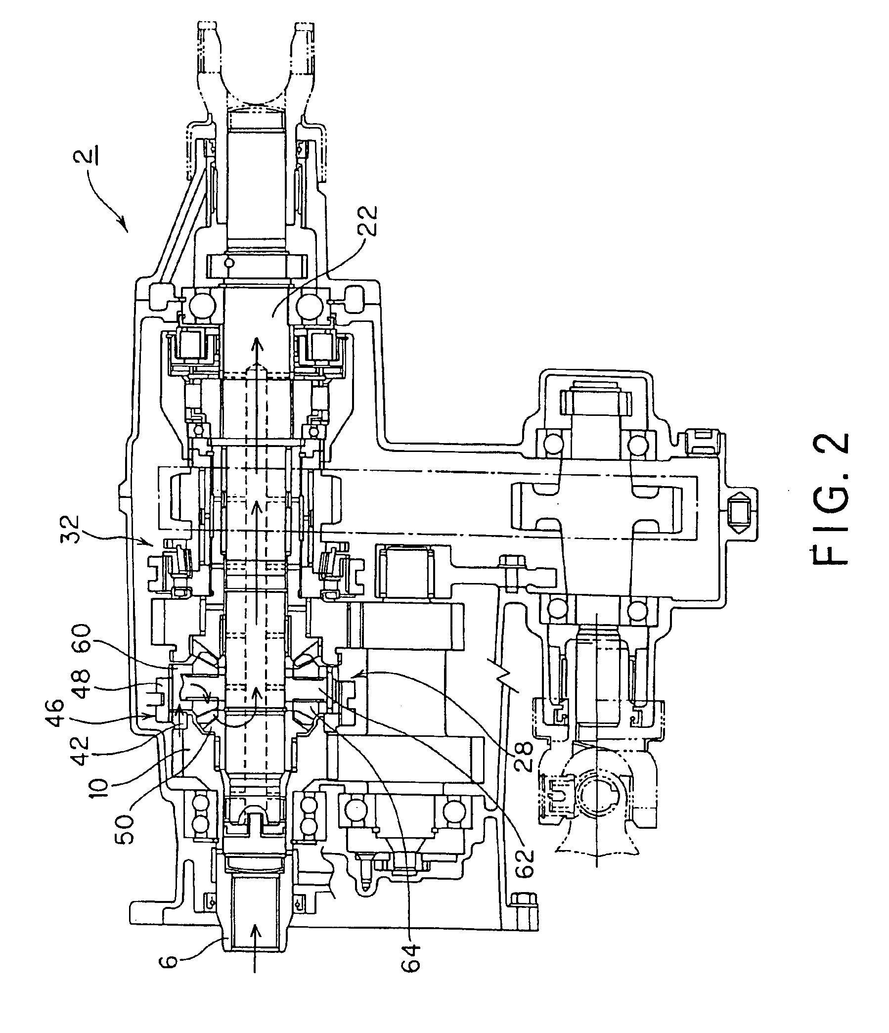
[0015]FIGS. 1-5 illustrate an embodiment of this invention. FIG. 1 shows a transfer arrangement 2. The transfer arrangement 2 is connected to a change-speed transmission (not shown) of an internal combustion engine as a power source which is conventionally disposed longitudinally and toward the front of a four-wheel drive vehicle (not shown). The transfer arrangement 2 supports an input shaft 6 through an input shaft bearing 8 in a transfer case or housing 4. The input shaft 6 has a front end thereof connected to an output shaft (not shown) of the change-speed transmission (not shown). The other or rear end of input shaft 6 has a first gear 10 fixed, here integrated, thereon for changing speed. The gear 10 is part of a transmission which converts the rotation of input shaft 6 into high and low speeds, as explained below.

[0016]In the transfer case 4, a countershaft 12 is supported in parallel with the input shaft 6 through a bearing 18. The countershaft 12 integrates a first counter ...


PUM


Abstract

A transfer arrangement for a four-wheel drive vehicle having an input shaft, a transmission, and a center differential. The transmission includes a first gear attached to the input shaft, a first counter gear attached to a countershaft in parallel with the input shaft to receive the rotation of the first gear, a second counter gear fixed to the countershaft and rotating therewith, and a second gear aligned with the input shaft and rotatably supported along the input shaft to receive the rotation of the second counter gear. High speed-side and low speed-side output parts are attached to the first and second gears respectively. The center differential is disposed between the high speed-side and low speed-side output parts. An engaging device disposed adjacent the center differential selectively engages with the high speed-side and low speed-side output parts.

Description

FIELD OF THE INVENTION[0001]This invention relates to a power transfer arrangement for a four-wheel drive vehicle, and more particularly to a transfer arrangement for a four-wheel drive vehicle which eliminates a space for a hub dedicated for a transmission along with a connecting shaft for connection between the transmission and a center differential so as to reduce the axial length of the transfer arrangement.BACKGROUND OF THE INVENTION[0002]Four-wheel drive vehicles are equipped with a transmission to convert the driving force of an internal combustion engine, and a transfer arrangement to distribute the power or driving force input from the transmission to two output shafts. Some four-wheel drive vehicles are equipped with a center differential to permit the two output shafts to turn at different speeds.[0003]Examples of four-wheel drive wheels of the above type are illustrated by JP Laid-Open No. H02-204133, JP Laid-Open No. H05-42838, JP Laid-Open No. H06-17889, and JP Laid-Op...

Claims


Application Information

Patent Timeline
Patent Type & Authority Patents(United States)
IPC IPC(8): B60K17/344B60K17/346B60K17/35F16H48/08F16H48/20F16H48/38
CPCB60K17/346B60K17/3467
Inventor YAMADA, HIROAKI
Owner SUZUKI MOTOR CORP
Why Eureka
Try Eureka