Variable-length needle covering device of an injection device

a technology of injection device and needle cover, which is applied in the direction of infusion needles, intravenous devices, other medical devices, etc., can solve the problems of injection needles piercing the needle cover device, etc., and achieve the effect of relatively simple operation and secure operation

Inactive Publication Date: 2008-02-05
TECPHARMA LICENSING AG
View PDF13 Cites 3 Cited by
  • Summary
  • Abstract
  • Description
  • Claims
  • Application Information

AI Technical Summary

Benefits of technology

[0007]The present invention provides a needle covering device for an injection device that only requires a relatively small amount of space and may be securely operated. Operation of the needle covering device is relatively simple.
[0012]In one embodiment, the sections of the device may be telescopic. All of the sections may then be axially rigid. The individual sections of the needle covering device can be slid within each other in such a way that the needle covering device is variable in its length. In the retracted position, the individual telescopic sections can be arranged within each other (and not axially offset), thus achieving a smaller axial length of the needle covering device. Thus, a relatively small, efficient, non-buckling needle covering device is provided. The telescopic sections may be formed by sleeves that can be slid from a position in which the sleeves have a minimum axial overlap to a position in which they have a maximum, possibly complete, axial overlap. In the position of maximum overlap, the needle covering device is in the retracted position. The individual telescopic sections or sleeves may be of equal length and come to rest directly side by side in the retracted position. A telescopic needle covering device according to this embodiment includes at least two telescopic sections.
[0013]In one embodiment, when the cover is in the extended position, the other telescopic section protrudes out of the casing or adapter section and the front telescopic section protrudes out of the second telescopic section. In the retracted position, both telescopic sections are slid back into the casing or adapter section. The adapter section is fixedly connected to the casing so as to form a guide for a telescopic section adjacent to and movable with respect to the adapter section. The adapter section can be formed by a telescopic receptacle. The telescopic sections can be slid into the adapter section to move to the retracted position. Such a needle covering device may be connected to a conventional injection device lacking a needle covering device, without significant changes having to be made to said injection device. Thus, when the covering device is not slid into the casing of the injection device it may still secure guidance of the needle covering device.
[0014]In one embodiment, the telescopic sections may be axially guided in a straight line. The telescopic sections may be sleeve-shaped. The outer and / or inner surface areas of the telescopic sections can form the guiding areas. The telescopic sections may also be non-rotationally axially guided. Adjacent telescopic sections may include grooves and protrusions respectively, that interconnect with each other to prevent the telescopic sections from rotating. Instead of circular sleeves, the telescopic sections can instead be formed by oval or cornered sleeves that also prevent rotation.

Problems solved by technology

If the syringe is placed on the skin at any non-perpendicular angle to the surface of the skin, the injection needle may pierce the needle covering device.

Method used


Image

  • Variable-length needle covering device of an injection device
  • Variable-length needle covering device of an injection device
  • Variable-length needle covering device of an injection device

Examples


Embodiment Construction

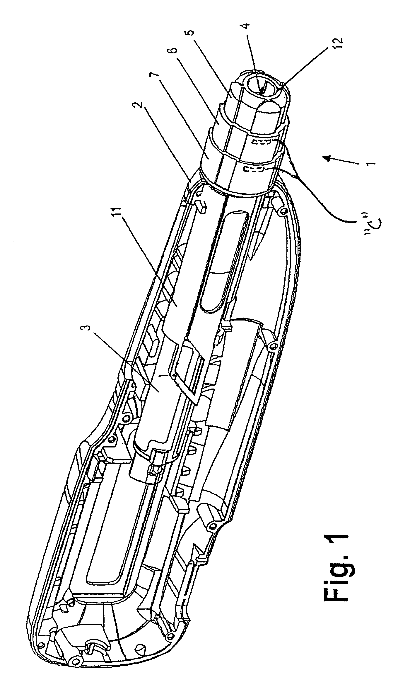
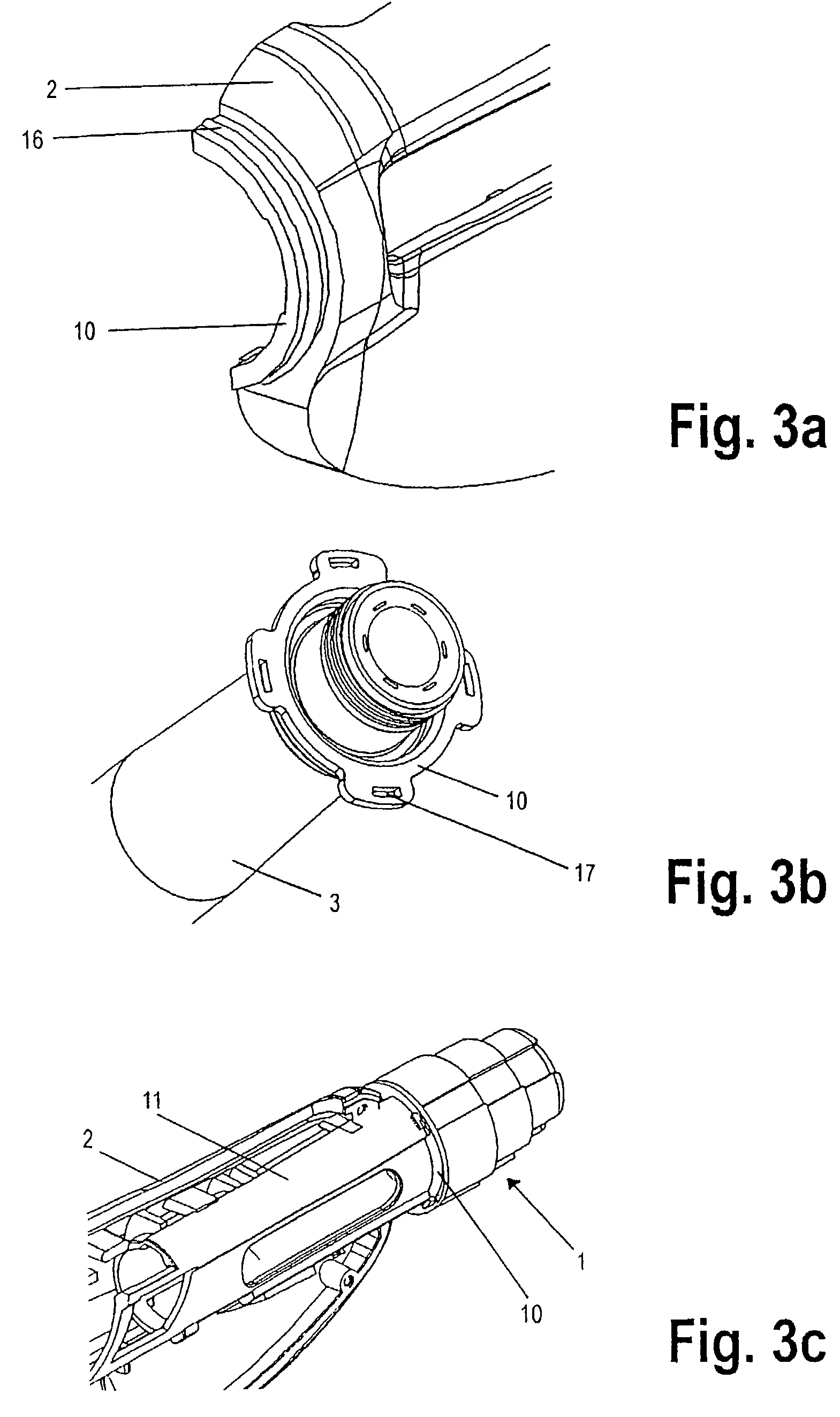
[0029]Referring to FIG. 1, a casing 2 is illustrated. The casing 2 has two casing halves (only one such half being shown). An ampoule 3 is accommodated in the casing 2 as a reservoir for a product fluid to be administered. The ampoule 3 is held in the casing 2 by a guiding tube 11 which is fixedly connected to the casing 2. The ampoule 3 comprises an outlet end and a piston, wherein the piston is pressed towards the outlet end in order to deliver the fluid product. An injection needle 4 has a fluid connection to the outlet end of the ampoule 3. The fluid product is injected via the injection needle 4.

[0030]The injection needle 4 is at least partially surrounded by a needle covering device 1, such that the injection needle 4 is substantially obscured from view.

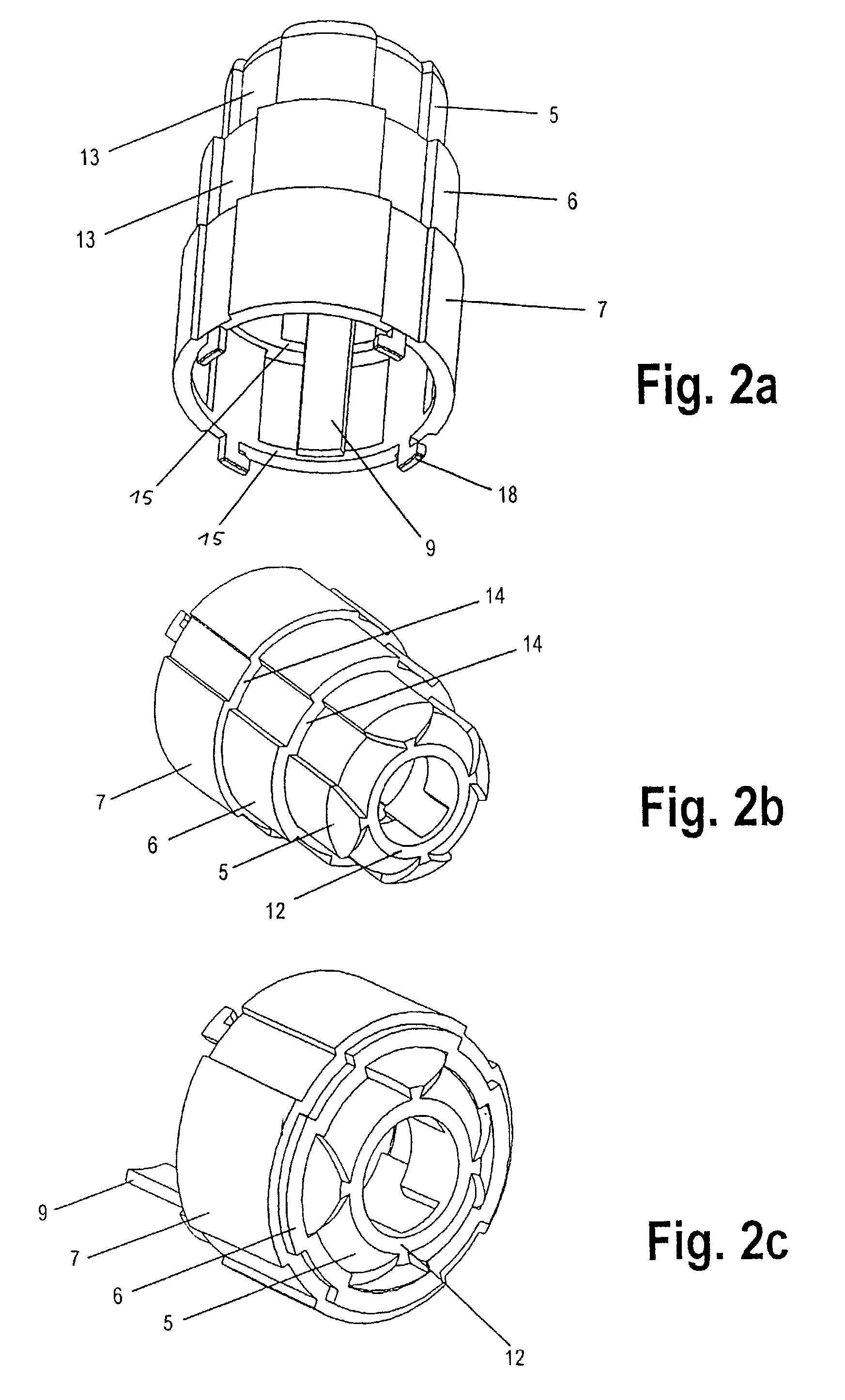
[0031]In the embodiment illustrated in FIG. 1, the needle covering device 1 is telescopic. The needle covering device 1 is fixedly connected to the casing 2 via a rear section 7, referred to as an adapter section 7. An intermed...


PUM


Abstract

The invention relates to a needle covering device of an injection device, the injection device including a casing comprising a reservoir, in particular an ampoule, for a product fluid to be administered, and an injection needle for injecting the product fluid from the reservoir, wherein the device surrounds the injection needle in an extended position and exposes the injection needle in a retracted position. The device comprises a passage for the injection needle, a front section via which the device is placed on an injection point, and another section which is nearer to the casing than the front section is, at least in the extended position. The sections can be moved axially relative to the casing and relative to each other, such that the device is variable in its length, the front section being guided in a straight line on the casing.

Description

CROSS-REFERENCE TO RELATED APPLICATION(S)[0001]This application claims the benefit of PCT Application No. PCT / CHO1 / 00112, filed on Feb. 22, 2001, which claims priority to German Application No. DE 100 09 815.0, filed on Mar. 1, 2000, both of which are herein incorporated by reference in their entirety.BACKGROUND OF THE INVENTION[0002]1. Field of the Invention[0003]The invention relates to a variable-length needle cover for an injection device.[0004]2. Description of the Related Art[0005]Many users of injection devices have a psychological aversion (so-called “needle phobia”) to injection needles such as those used for injecting a fluid product. Patients who actually inject the fluid product themselves often have an inhibition threshold that has to be overcome when injecting the needle. In order to reduce this inhibition threshold, needle covers have been provided for injection devices.[0006]A variable-length needle covering device for a syringe is disclosed in WO 96 / 11026. The needl...

Claims


Application Information

Patent Timeline
Patent Type & Authority Patents(United States)
IPC IPC(8): A61M5/00A61M5/20A61M5/32A61M5/46
CPCA61M5/3257A61M5/3271A61M5/20A61M5/46A61M2005/2013A61M2005/3267A61M2205/59
Inventor BRAND, ANDREASSTEINER, REMO
Owner TECPHARMA LICENSING AG
Why Eureka
Try Eureka