Pitch system for a wind turbine rotor

a technology for wind turbines and rotors, which is applied in the direction of bearings, shafts, motors, etc., can solve the problems of relatively high cost and relatively complex construction of rotors, and achieve the effect of reducing construction costs, simple and cheaper toothing, and greater stiffness

Active Publication Date: 2017-02-14
GE RENEWABLE TECH WIND BV
View PDF13 Cites 2 Cited by
  • Summary
  • Abstract
  • Description
  • Claims
  • Application Information

AI Technical Summary

Benefits of technology

[0011]The two bearings and the intermediate body provide a pitch system that has a good stiffness and is simple and cost effective, since each bearing may be fairly simple and of relatively small axial length, and therefore a relatively standard part, while the intermediate body may be manufactured with materials and qualities that can be more economic and easier to manufacture than bearings, and especially than known large multi-row pitch bearings.
[0012]The intermediate body may provide two different effects. In the first place, it may reinforce and stiffen the second bearing, and particularly the inner race thereof, which is subject to a larger bending moment due to the wind loads than the first bearing, and therefore reduces the strain of said second bearing and the risk e.g. of contact ellipse truncation that may arise in bearings of large diameter such as pitch bearings, due to their relatively small stiffness.
[0013]In the second place, the intermediate body can be made of a dimension that provides a suitable length for the studs that attach the pitch system to the blade and to the hub, and therefore makes it easier to employ studs with good fatigue behaviour.
[0015]The intermediate body may also be employed for the pitch drive, since it is simpler and cheaper to provide a toothing for the drive on the intermediate body than on a bearing race.
[0016]The presence of two separate bearings also makes it easier to provide each of them with features best suited to its position in the assembly; for example, in embodiments of the invention the first bearing may be of greater stiffness than the second bearing, for example it may have a larger axial length.

Problems solved by technology

On the other hand, pitch bearings must stand several forces and moments, and in particular the bending moment caused by the force of the wind on the blades, that tends to strain especially the region of the bearing remote from the hub.
However, the axial length of such pitch bearings is relatively large, and at the same time they need to have a suitable stiffness to withstand the loads; their construction is therefore relatively complex, and their cost rather high.

Method used


Image

  • Pitch system for a wind turbine rotor
  • Pitch system for a wind turbine rotor
  • Pitch system for a wind turbine rotor

Examples


Embodiment Construction

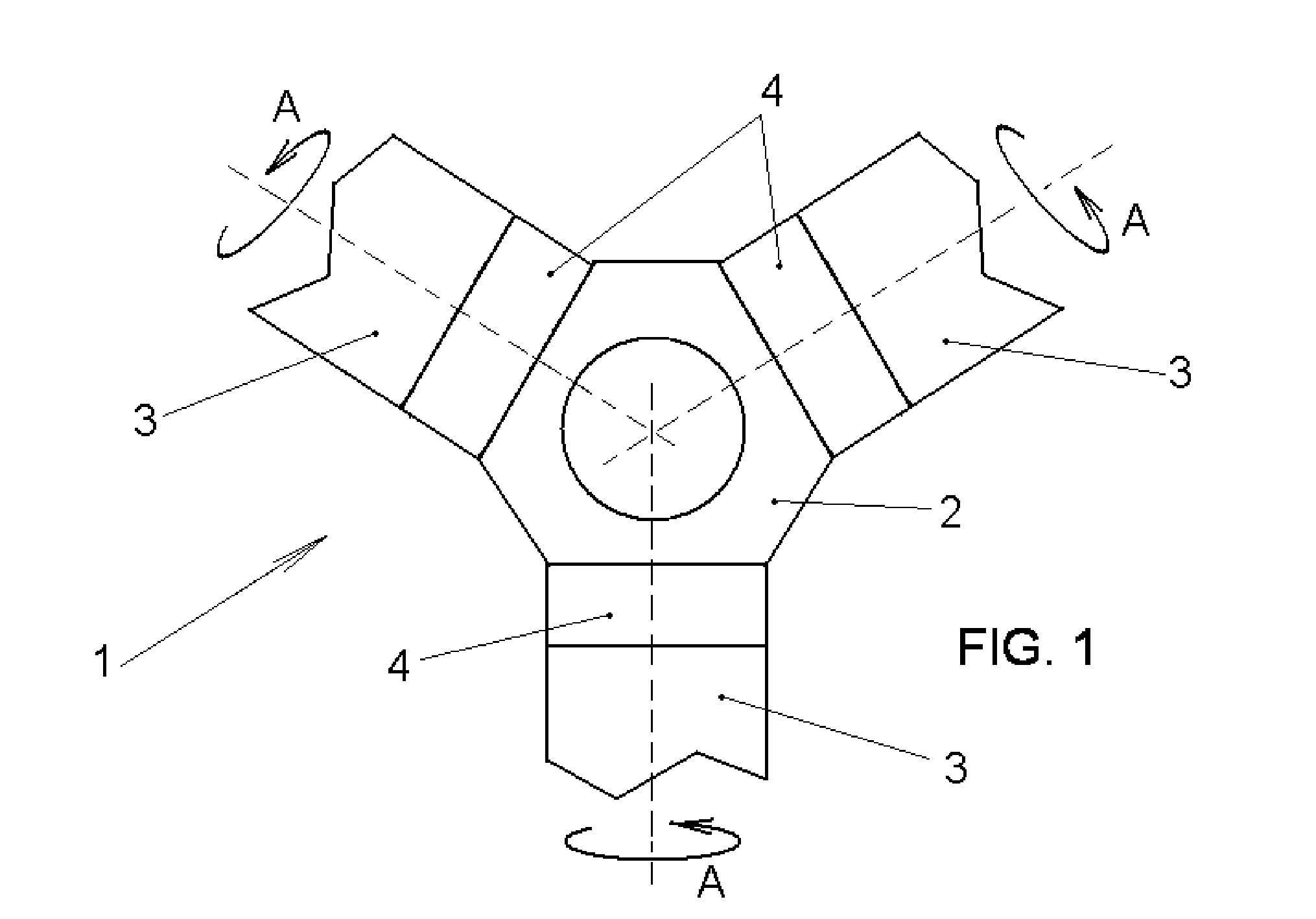
[0025]FIG. 1 shows a wind turbine rotor 1, which may have a hub 2 and three blades, of which only a root portion 3 is shown in the figure, each attached to the hub 2 by means of a pitch system 4 that allows rotation of each blade around its longitudinal axis, as shown by arrows A, such that the wind engages a larger or smaller surface of the blade.

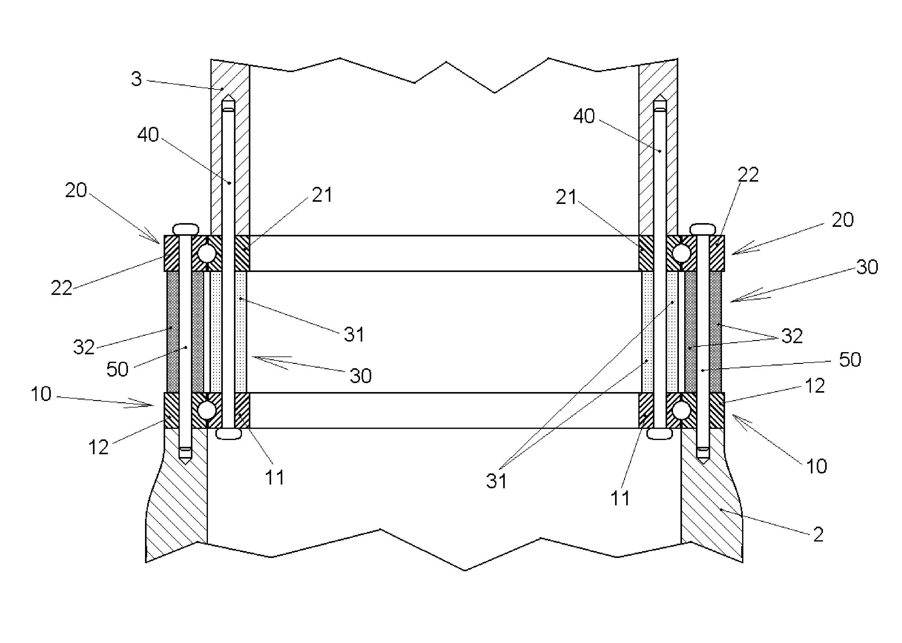
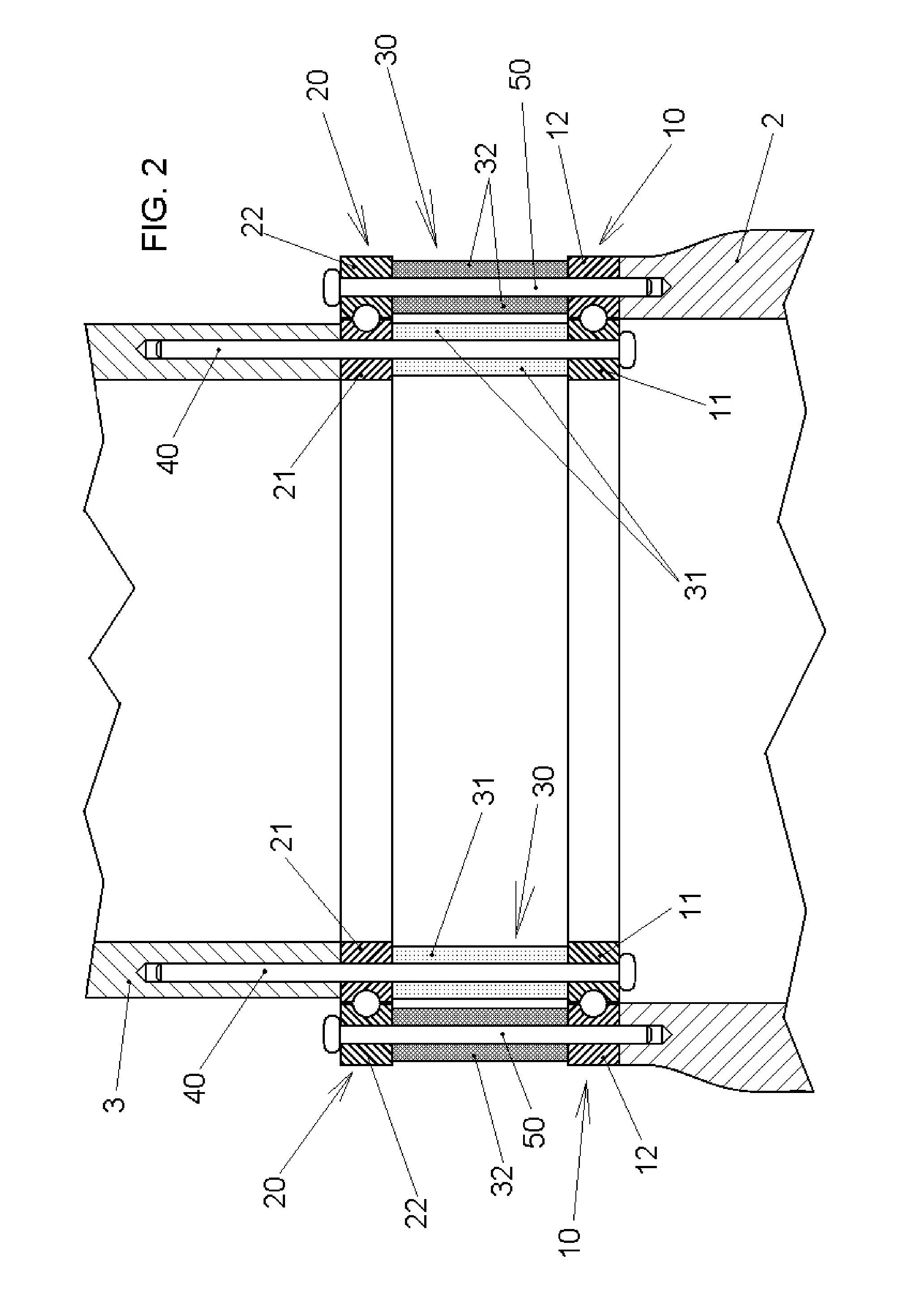
[0026]An embodiment of a pitch system 4 according to the invention is shown in FIG. 2. The pitch system comprises a first bearing 10 and a second bearing 20, the first bearing being arranged nearer to the hub 2. In this example, the inner race 11 and 21 of each bearing 10 and 20 is associated with the blade root portion 3, while the outer race 12 and 22 of each bearing 10 and 20 is associated with the hub 2, although in other embodiments the hub may be attached to the inner races and the blade may be attached to the outer races.

[0027]The pitch system 4 further comprises an intermediate body 30, which is arranged between the first bearing 1...


PUM


Abstract

A pitch system for a wind turbine rotor, comprising a first bearing and a second bearing, each provided with an outer race, an inner race, and at least one row of rolling elements, the first and second bearings being adapted to be arranged between a hub and a blade root portion or extender, to allow rotation of the blade with respect to the hub, wherein the first bearing is adapted to be arranged nearer to the hub than the second bearing in the axial direction, the pitch system further comprising an intermediate body arranged between the first bearing and the second bearing in the axial direction, said intermediate body comprising at least a blade-side part extending between the race of the first bearing that is associated with the blade and the race of the second bearing that is associated with the blade.

Description

[0001]This application claims the benefit of European Patent Application EP 12382253.8 filed on 27 Jun. 2012 and U.S. Provisional Patent Application Ser. No. 61 / 693,696 filed on 27 Aug. 2012, the disclosures of which are hereby incorporated by reference in their entirety for all purposes.[0002]The present invention relates to a pitch system for a wind turbine rotor, and to a wind turbine having such a pitch system.BACKGROUND ART[0003]Known wind turbines have a rotor generally comprising a hub and three turbine blades mounted on the hub. The load on the rotor may be controlled by pitching the blades, i.e. by rotating each blade around its longitudinal axis (from root to tip) and cause the wind to engage a larger or smaller surface of the blade.[0004]For the purpose of pitching the blades, each blade is mounted on the hub by means of a pitch system, which in known turbines comprises a pitch bearing arranged between the hub and the blade, and a pitch drive which may include a motor, a ...

Claims


Application Information

Patent Timeline
Patent Type & Authority Patents(United States)
IPC IPC(8): F03D7/02F03D1/06
CPCF03D7/0224F03D1/0658F03D80/70Y02E10/721Y02E10/722Y02E10/723F16C35/06F16C19/54F16C2360/31Y02E10/72
Inventor PASQUET, PIERRE
Owner GE RENEWABLE TECH WIND BV
Why Eureka
Try Eureka