Flow controller

a flow controller and controller technology, applied in the field of spread-adjusting flow controllers, can solve the problem of very compact design of the rate controlling module, and achieve the effect of reducing the installation space requirement, and reducing the advantageous effect of the installation space requiremen

Active Publication Date: 2017-05-16
IMI HYDRONIC ENG INT SA
View PDF29 Cites 3 Cited by
  • Summary
  • Abstract
  • Description
  • Claims
  • Application Information

AI Technical Summary

Benefits of technology

[0008]The particular advantage of the invention is that by providing the first flow-through opening on the outer side, in particular an axial length of the rate regulation module can be made smaller and therefore the installation space requirement for accommodating the rate regulating module decreases. It is achieved in this respect to construct the flow controller of the invention with a standard housing, which is routinely used within the scope of installing heating systems and is made, for example, in the shape of a T-piece. The compact design in this respect reduces the installation space requirement in the new installation of heating systems. Moreover, the conversion of existing heating systems and the first-time provision of a flow controller according to the invention in these existing systems are supported. It is achieved in particular to use the housing of a thermostatic valve and in addition to realize the flow rate control in this housing.
[0009]According to an exemplary embodiment of the invention, the handle acts together with a regulating insert disposed movable with respect to the sleeve. The effective cross section of the first flow-through opening is defined depending on a relative position of the sleeve and regulating insert. The regulating insert can be provided in particular rotatable with respect to the sleeve or the cup of the rate controlling module. The installation space requirement is advantageously reduced further, when the regulating insert is provided rotatable with respect to the sleeve or cup. In particular, the lack of an axial displacement makes the design of the rate controlling module very compact, because the rotation can be realized within an active space of the rate controlling module, said space being defined by the cup or sleeve. In particular, the installation space requirement or the size of the rate controlling module does not change as a function of the value of the flow volume preadjustment.
[0010]According to an embodiment of the invention, the regulating insert engages with a control section of the same in the sleeve. An inner cylindrical surface of the sleeve in this case lies flat against an outer cylindrical surface of the control section. In particular the control section of the regulating insert has a control contour which depending on a rotary position of the regulating insert completely releases the first flow-through opening for the hot medium or in any case covers it partially. The preadjustment for the flow volume of the heating medium then results depending on the rotary position. Advantageously, a very fine adjustment of the cross section of the first flow-through opening can be realized by providing the control contour and by the suitable geometric configuration of the same. The flow volume can be varied over a broad range in this regard and preadjusted precisely.
[0011]According to an embodiment of the invention, the sleeve can surround the cup on the outer side in each case in sections. The sleeve is provided in particular immovable and the cup is held axially movable in the sleeve. Advantageously the axial movement of the cup occurs relative to the sleeve within the active space of the rate regulating module. The compact design can be promoted further and it is possible to integrate the rate regulating module into a merely small installation space. The sleeve in this regard defines the volume for the active space of the rate regulating module. It has a substantial effect on the installation space requirement of the rate regulating module. The movably held cup in contrast is surrounded by the sleeve. It has no or at best a minor effect on the size and compactness of the rate regulating module.
[0012]The second flow-through opening provided for regulating the preadjusted flow, according to an embodiment of the invention, can be formed between the regulating insert and the cup. In particular, the second flow-through opening has the shape of an axial gap. The axial gap can be formed as a cylindrical annular gap, whereby the cylindrical annular gap has a constant axial width. The width of the axial gap and thereby the cross section of the second flow-through opening varies depending on the pressure conditions in the rate regulating module. The very sensitive regulation of the flow, preadjusted and defined by the cross section of the first flow-through opening, for the heating medium is achieved in this respect.
[0013]The regulating insert provides a supporting section for guiding the cup movable relative to the sleeve. The cup can be connected to the sleeve on the outer cylindrical side in the area of a first supporting site and to the supporting section of the regulating insert in the area of a second supporting site on the inner cylindrical side. The first supporting site and the second supporting site can be provided axially spaced apart from one another. Advantageously, a very compact design results by supporting the cup on the sleeve, on the one hand, and on the supporting section of the regulating insert, on the other. Moreover, a relative position of the cup to the sleeve results, on the one hand, and to the regulating insert, on the other. As a result, tolerances which may have a negative effect on the function of the flow controller are reduced or eliminated. Uniform flow conditions in the rate regulating module develop, moreover, which promote safe operation and reliability and counteract jamming of the cup.

Problems solved by technology

In particular, the lack of an axial displacement makes the design of the rate controlling module very compact, because the rotation can be realized within an active space of the rate controlling module, said space being defined by the cup or sleeve.

Method used


Image

  • Flow controller
  • Flow controller
  • Flow controller

Examples


Embodiment Construction

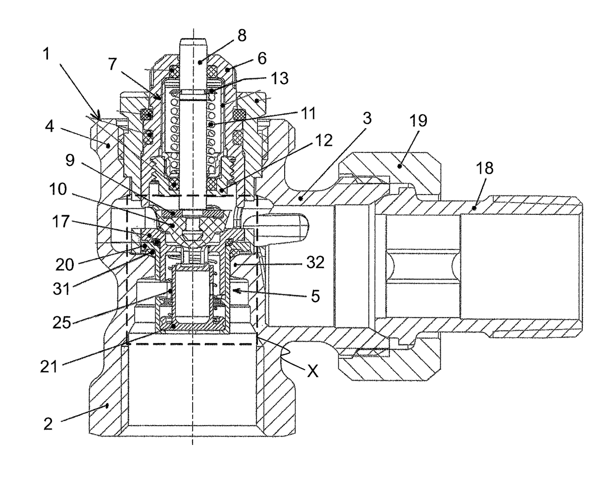
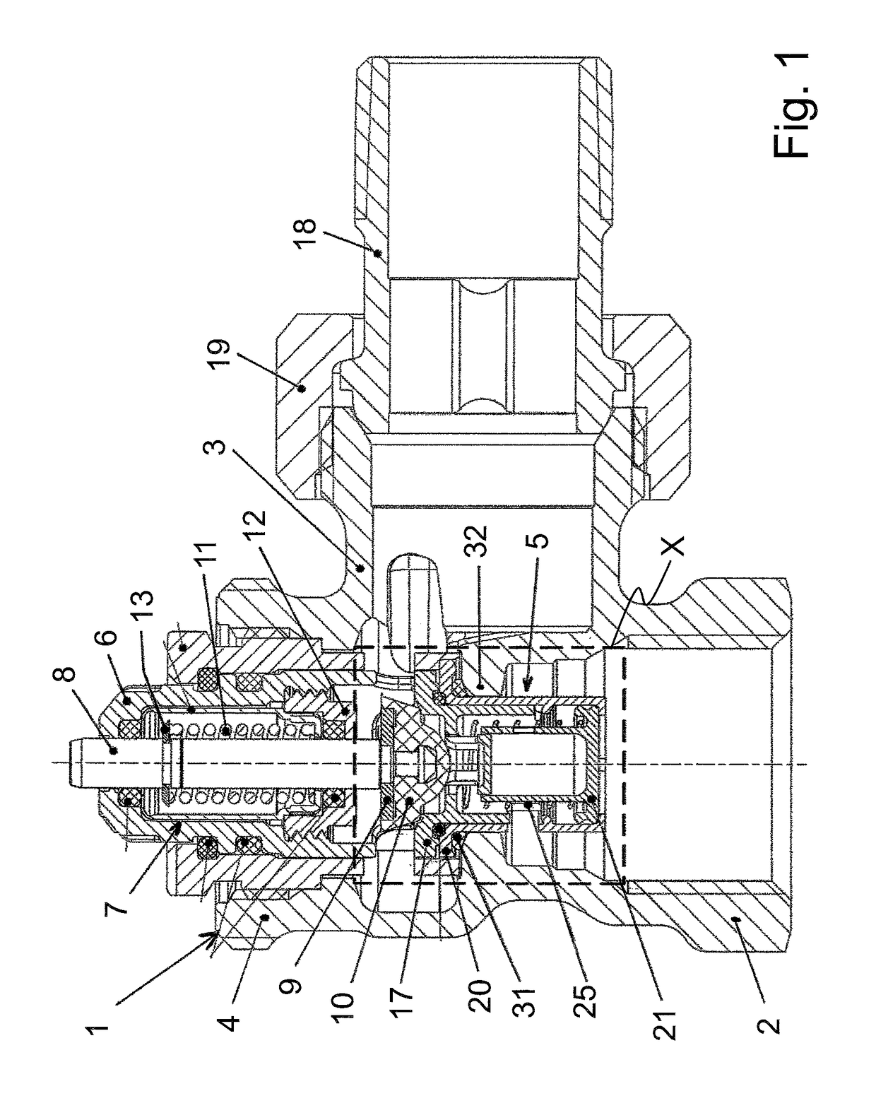
[0018]A flow controller for a heating system according to FIG. 1 comprises as essential components a housing 1 with an inlet connection 2 for a heating medium, with an outlet connection 3, and with a preadjustment connection 4, as well as a rate regulating module 5 and a handle 6. A flow volume for the heating medium is changed with use of rate regulating module 5. The change in the flow volume occurs as a function of a preadjustment of rate regulating module 5 and a pressure difference. The preadjustment is made via handle 6.

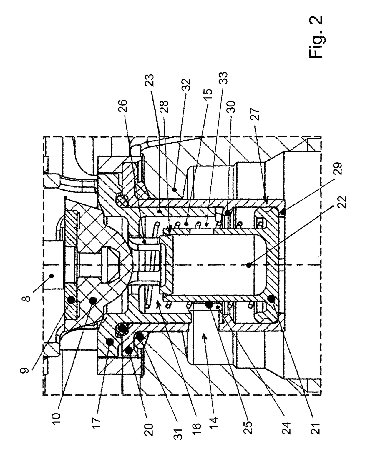
[0019]Further, a temperature control module 7 of a temperature controller is provided in housing 1 of the flow controller. Temperature control module 7 comprises in particular a sensor pin 8 which is coupled to a temperature transmitter (not shown) and at whose end, facing rate regulating module 5, a plate 9 and a seal 10 retained at plate 9 are provided. Depending on a specified temperature and a temperature detected by the temperature sensor, sensor pin 8 is ...


PUM


Abstract

A flow controller for a heating system with a housing, which has an inlet connection for a heating medium, an outlet connection for the heating medium, and a preadjustment connection, with a rate regulating module, and with a handle, which acts together with a movably disposed structural element of the rate regulating module to preadjust the flow. To change the preadjustment of the flow via the handle, an effective cross section of a first flow-through opening for the heating medium can be adjusted and to regulate the preadjusted flow of the heating medium, a sleeve of the rate regulating module and a cup of the rate regulating module are disposed axially movable to one another. The inflow to the rate regulating module occurs on an outer side via the first flow-through opening which is provided on the sleeve and upstream of the second flow-through opening.

Description

[0001]This nonprovisional application claims priority under 35 U.S.C. §119(a) to European Patent Application No. EP 14181388.1, which was filed on Aug. 19, 2014, and which is herein incorporated by reference.BACKGROUND OF THE INVENTION[0002]Field of the Invention[0003]The present invention relates to a preadjustable flow controller for a heating system with a housing, which has an inlet connection for a heating medium, an outlet connection for the heating medium, and a preadjustment connection, with a rate regulating module, which depending on a preadjustment and a pressure difference changes a flow for the heating medium, and with a handle, which acts together with a movably disposed structural element of the rate regulating module to preadjust the flow, whereby to change the preadjustment of the flow via the handle, an effective cross section of a first flow-through opening for the heating medium can be adjusted and whereby to regulate the preadjusted flow of the heating medium, a...

Claims


Application Information

Patent Timeline
Patent Type & Authority Patents(United States)
IPC IPC(8): G05D7/01F24D19/10F16K1/52
CPCG05D7/014F24D19/1015F16K1/526F24D2220/0264Y10T137/7788F16K1/52F16K17/30F16K31/002F24D19/10G05D7/01
Inventor ESSFELD, FRITZHENKE, BERNHARDSCHMIDT, CARINATRANTHAM, JOHN
Owner IMI HYDRONIC ENG INT SA
Why Eureka
Try Eureka