Automatic transmission

a transmission and automatic technology, applied in mechanical equipment, transportation and packaging, gearbox installation, etc., can solve the problems of increased manufacturing cost, increased weight, and installation of the transmission on the vehicle, and achieve the effect of reducing the effect of shift shocks and easy shifting control

Inactive Publication Date: 2005-05-03
TOYOTA JIDOSHA KK
View PDF19 Cites 73 Cited by
  • Summary
  • Abstract
  • Description
  • Claims
  • Application Information

AI Technical Summary

Benefits of technology

[0012]With the automatic transmission constructed as described above, the seven forward speeds are provided by the first transmitting portion, the second transmitting portion mainly including two planetary gear sets, four clutches and two brakes. Thus, the automatic transmission is made light-weight and compa

Problems solved by technology

The automatic transmission as disclosed in JP-A-2000-266138, which uses four planetary gear sets, has a relatively large axial length, and may suffer from a difficulty in installing the transmis

Method used


Image

  • Automatic transmission
  • Automatic transmission
  • Automatic transmission

Examples


first embodiment

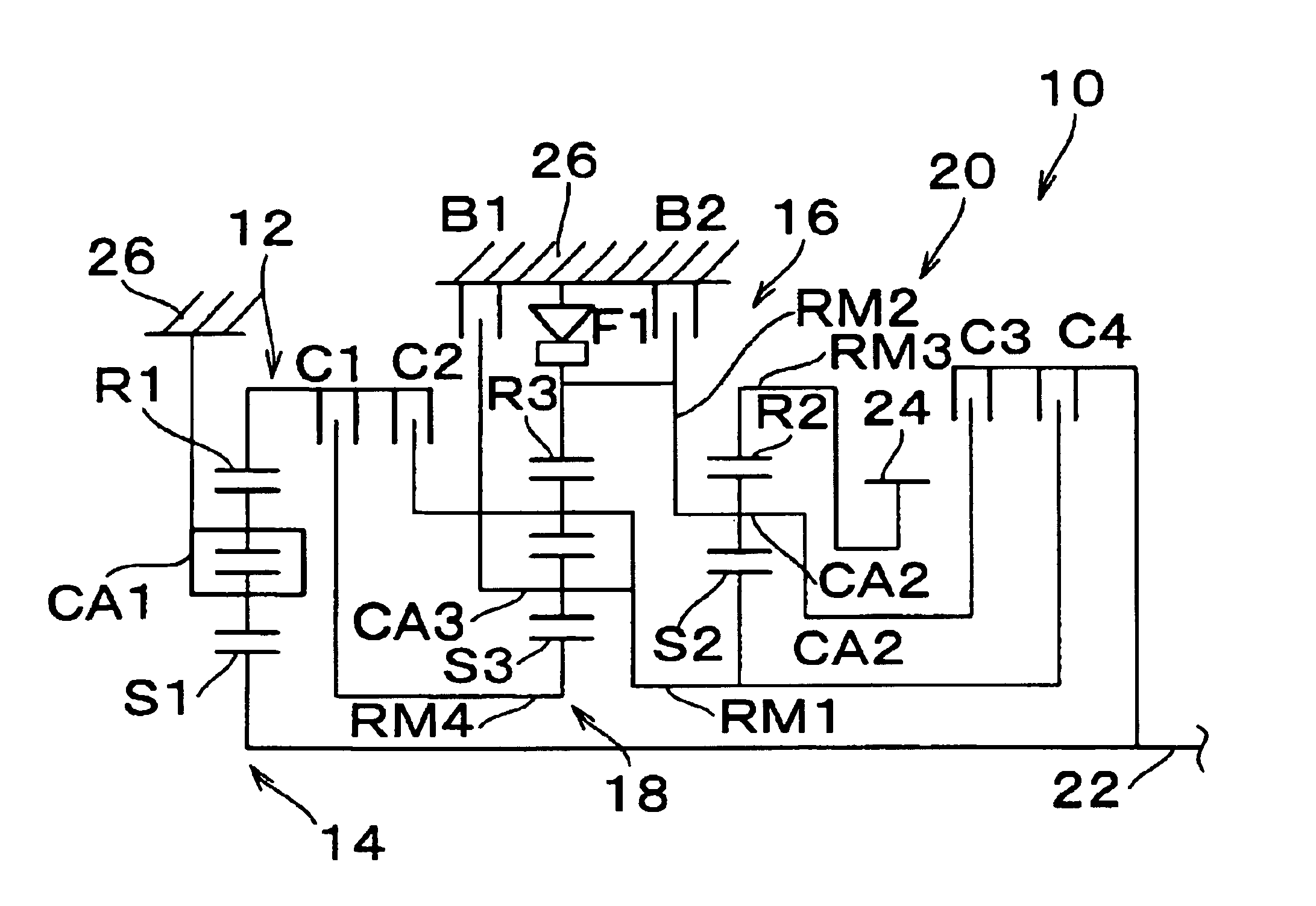
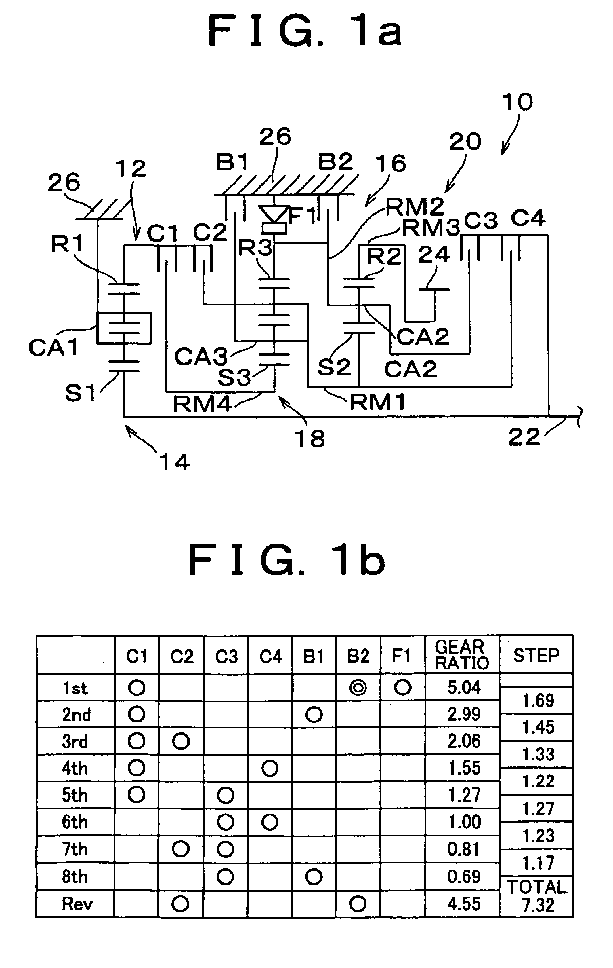
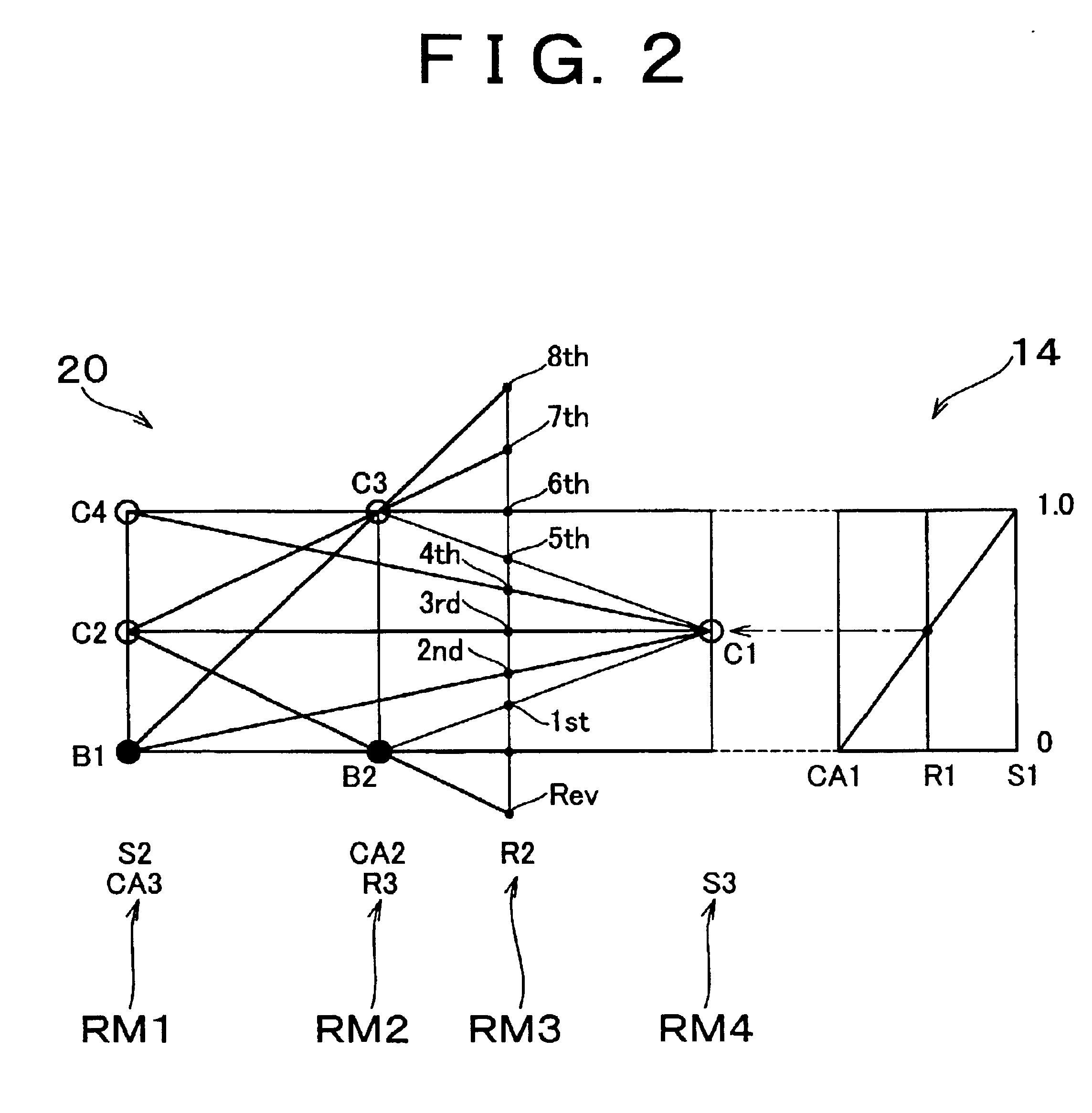
[0040]FIG. 1a schematically shows an automatic transmission 10 of a motor vehicle according to the first embodiment of the invention, and FIG. 1b is an operation table useful for explaining the relationship between engaging elements and gear ratios when a plurality of gear stages are established. The automatic transmission 10 is mounted in the lateral direction in a vehicle, such as a FF vehicle, and includes a sub-transmitting portion 14 and a main transmitting portion 20. The sub-transmitting portion 14 mainly includes a first planetary gear set 12 of a double-pinion type, and the main transmitting portion 20 mainly includes a second planetary gear set 16 of a single-pinion type and a third planetary gear set 18 of a double-pinion type. The automatic transmission 10 thus constructed transmits rotary power from an input shaft 22 to an output gear 24 while changing the speed of rotation. The sub-transmitting portion 14 is the first transmitting portion whereas the main transmitting ...

second embodiment

[0058]FIG. 4a is a schematic vehicle showing an automatic transmission 40 of a motor vehicle according to the second embodiment of the invention. FIG. 4b is an operation table useful for explaining the relationship between engaging elements and gear ratios when a plurality of gear stages are established. FIGS. 1a, 1b, and 5 correspond to FIGS. 1a, 1b, and 2, respectively.

[0059]The automatic transmission 40 is to be installed on in the longitudinal direction of a vehicle such as a FR vehicle. With the automatic transmission 40, rotary power is transmitted from an internal combustion engine as a driving power source to the input shaft 22 via a torque converter 42, and is output from the output shaft 32 to the driving wheels via the propeller shaft and so on. The main transmitting portion 20 has substantially the same construction as the automatic transmission of the above-described first embodiment, but positions of the second planetary gear set 16 and the third planetary gear set 18 ...

third embodiment

[0062]FIG. 7a is a schematic view showing an automatic transmission 50 of a motor vehicle according to the third embodiment of the invention. FIG. 7b is an operation table useful for explaining the relationship between engaging elements and gear ratios when a plurality of gear stages are established. FIGS. 7a, 7b, and 8 correspond to FIGS. 1a, 1b, and 2, respectively.

[0063]The automatic transmission 50 is different from the automatic transmission 40 shown in FIG. 5 in respect of the construction of the sub-transmitting portion 52. More specifically, the sub-transmitting portion 52 of the automatic transmission 50 mainly includes the first planetary gear set 54 of a single pinion type, in which the ring gear R1 is coupled to and rotated by the input shaft 22, and the sun gear S1 is fixed to the case 26 and is thus inhibited from rotating, while the carrier CA1, serving as an intermediate output member, is rotated at a reduced speed as compared with that of the input shaft 22, to outp...


PUM


Abstract

An automatic transmission includes a first rotating element provided by coupling a sun gear of a second planetary gear set and a carrier of a third planetary gear set to each other, a second rotating element provided by coupling a carrier of the second planetary gear set and a ring gear of the third planetary gear set to each other, a third rotating element provided by a ring gear of the second planetary gear set, and a fourth rotating element provided by a sun gear of the third planetary gear set. The first rotating element and the second rotating element are coupled to a case by first and second brakes, the fourth and first rotating elements are coupled to a ring gear of a first planetary gear set via first and second clutches, the second and first rotating elements are coupled to an input shaft via third and fourth clutches, and the third rotating element is integrally coupled to an output gear, so that the automatic transmission can provide eight forward gear stages by changing a combination of two of the clutches and brakes which are engaged to each other.

Description

INCORPORATION BY REFERENCE[0001]The disclosure of Japanese Patent Application No. 2001-332177 filed on Oct. 30, 2001, including the specification, drawings and abstract is incorporated herein by reference in its entirety.BACKGROUND OF THE INVENTION[0002]1. Field of Invention[0003]The invention relates to an automatic transmission, and more particularly to an automatic transmission capable of providing seven or more forward gear stages or speeds by using three planetary gear sets and also capable of shifting from one gear stage to another gear stage by changing a combination of two different engaging elements, such as clutches and brakes, to be engaged.[0004]2. Description of Related Art[0005]Automatic transmissions of motor vehicles, each including a plurality of planetary gear sets, clutches and brakes, have been widely used. Japanese Laid-Open Patent Publication No. 2000-266138 (JP-A-2000-266138) discloses an example of such an automatic transmission which is able to provide seven...

Claims


Application Information

Patent Timeline
IPC IPC(8): F16H3/66F16H3/44F16H3/62
CPCF16H3/666F16H2200/0056F16H2200/2097F16H2200/201F16H2200/2048F16H2200/006
Inventor MIYAZAKI, TERUFUMIIIJIMA, YOSHIHIROTABATA, ATSUSHIHOJO, YASUOHOSHINO, AKIRA
Owner TOYOTA JIDOSHA KK
Why Eureka
Try Eureka