Catheter having improved rapid exchange junction

Inactive Publication Date: 2005-05-03
ABBOTT CARDIOVASCULAR
View PDF8 Cites 73 Cited by
  • Summary
  • Abstract
  • Description
  • Claims
  • Application Information

AI Technical Summary

Benefits of technology

[0014]The catheter of the invention has excellent ability to track within the patient's tortuous vasculature due to the improved rapid exchange junction. The fused section of the outer tubular member, with at least a section of the reinforcing tube extending therein and formed at least in part by the thickened wall portion of the outer tubular m

Problems solved by technology

One difficulty has been forming a rapid exchange junction with the desired characteristics of flexibility, kink resistance, and pushability (i.e., the ability to transmit force from

Method used


Image

  • Catheter having improved rapid exchange junction
  • Catheter having improved rapid exchange junction
  • Catheter having improved rapid exchange junction

Examples


Embodiment Construction

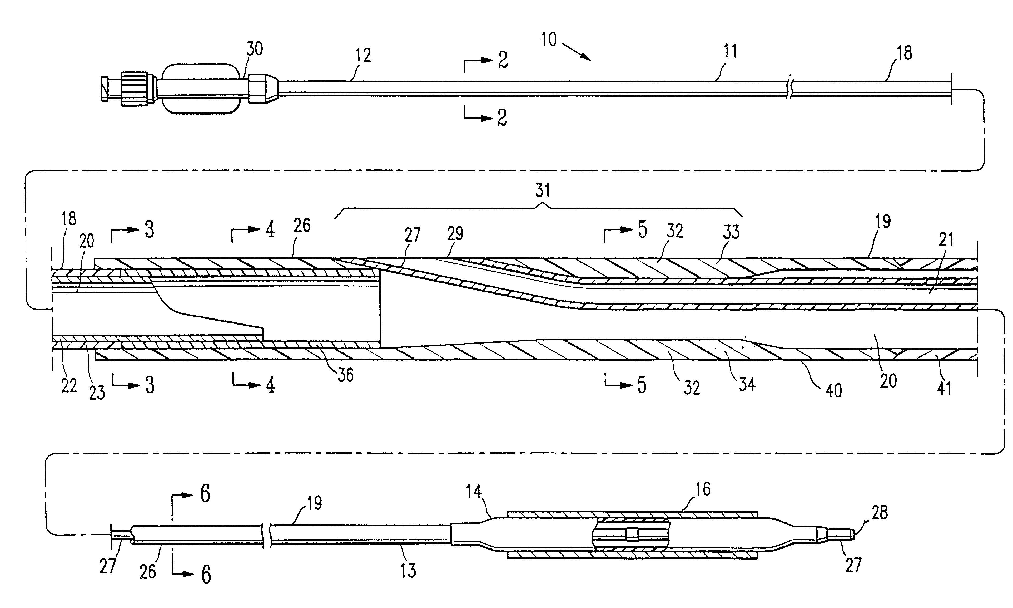
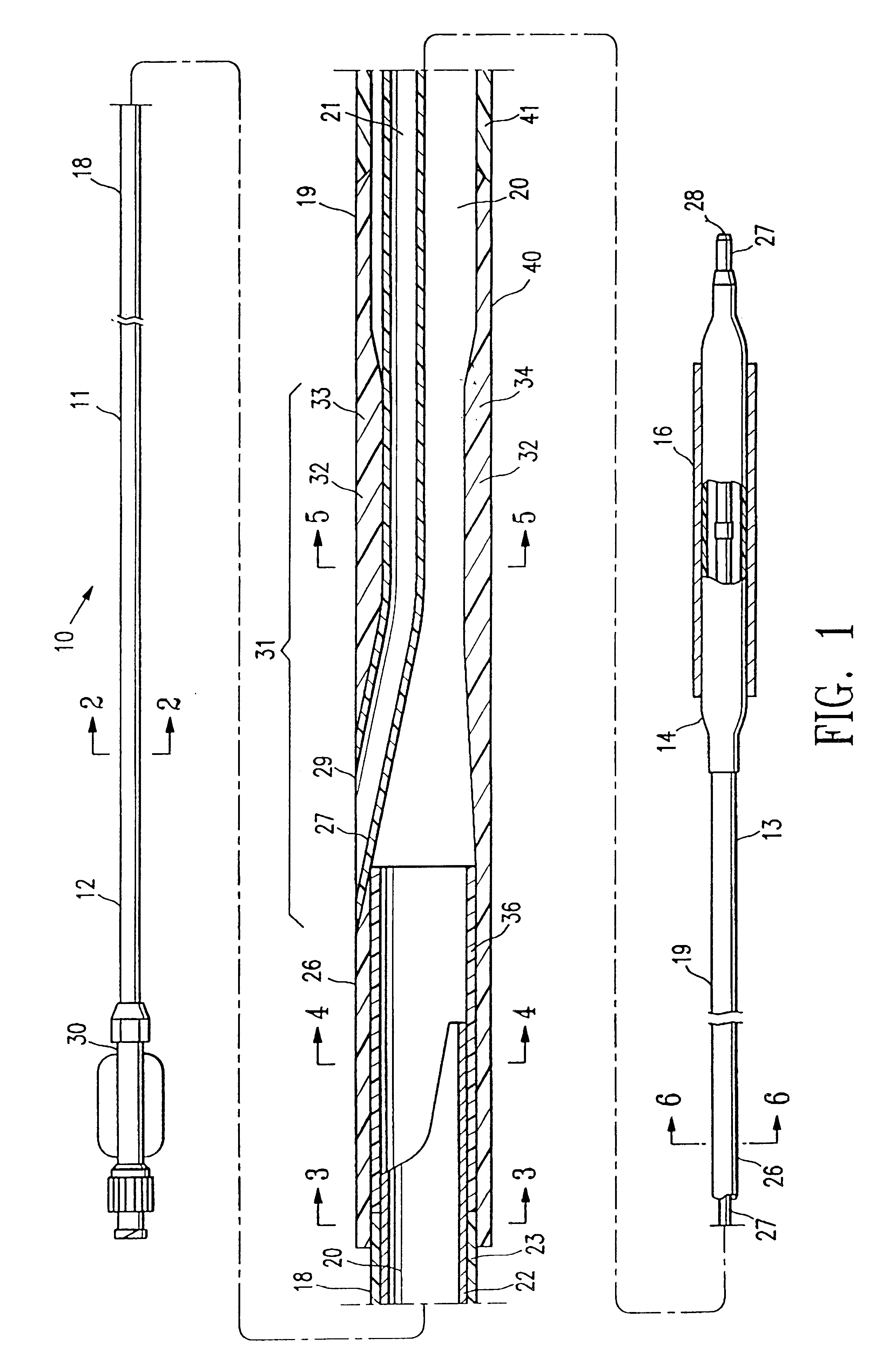
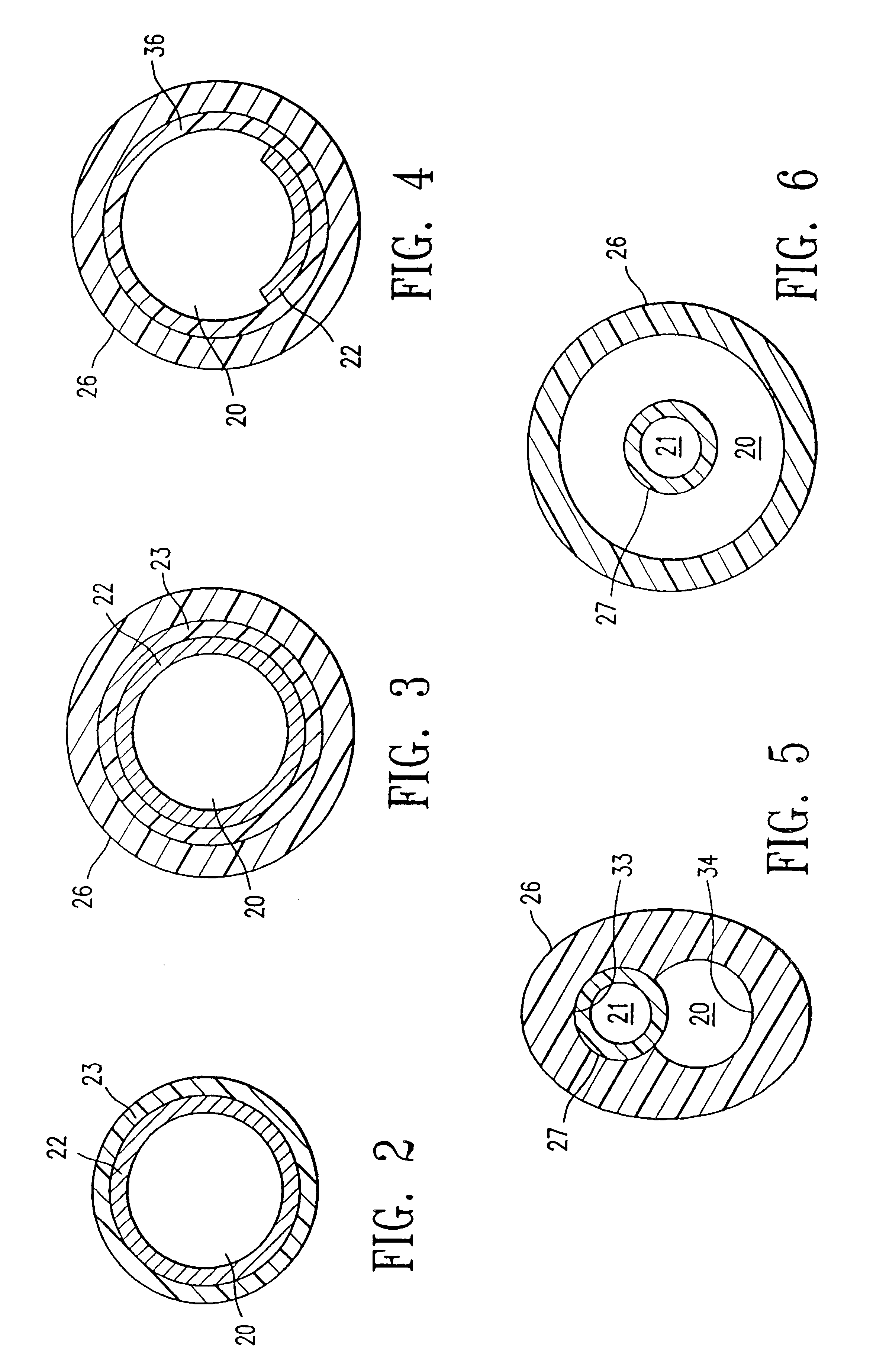
[0024]FIG. 1 illustrates rapid exchange type stent delivery balloon catheter 10 embodying features of the invention. Catheter 10 generally comprises an elongated catheter shaft 11 having a proximal end 12, a distal end 13, and an inflatable balloon 14 on a distal shaft section. An expandable tubular stent 16 is mounted on balloon 14 for implanting in the patient's body lumen. The shaft 11 has a proximal shaft section 18, a distal shaft section 19 at the distal end of the proximal shaft section, an inflation lumen 20, and a guidewire receiving lumen 21. The proximal shaft section 18 comprises a high strength tubular member 22 which is preferably a metallic tubular member such as a stainless steel or NiTi tubular member. In the embodiment illustrated in FIG. 1, a polymeric outer layer 23 is provided on the outer surface of the metallic tubular member 22. Polymeric outer layer 23 is preferably formed of a coextrusion of polyether block amide (PEBAX) and adhesive polymer such as Primaco...


PUM


Abstract

A balloon catheter, and preferably to a rapid exchange type balloon catheter, having a proximal shaft section, and a distal shaft section with an inner tubular member and an outer tubular member, the outer tubular member having a section which is bonded as by fusing or otherwise bonding. The bonded section extends along a thickened wall portion of the outer tubular member at the rapid exchange junction. A reinforcing member or tube extends within at least a section of the bonded section of the outer tubular member. In one embodiment, the reinforcing tube extends within at least a section of the thickened wall portion of the outer tubular member. The configuration provides a rapid exchange junction with improved kink resistance and flexibility for excellent trackability, and with a minimal decrease in the size of the inflation lumen at the rapid exchange junction for an improved shortened balloon inflation/deflation time.

Description

[0001]This application is a continuation of Ser. No. 10 / 002,477 filed Nov. 1, 2001.BACKGROUND OF THE INVENTION[0002]This invention generally relates to catheters, and particularly intravascular catheters for use in percutaneous transluminal coronary angioplasty (PTCA) or for the delivery of stents.[0003]In a typical PTCA procedure, a dilatation balloon catheter is advanced over a guidewire to a desired location within the patient's coronary anatomy, to position the balloon of the dilatation catheter within the stenosis to be dilated. The balloon is then inflated with radiopaque liquid at relatively high pressures (generally 4-16 atmospheres) to dilate the stenosed region of the diseased artery. One or more inflations may be needed to effectively dilate the stenosis. Additionally, a stent may be implanted within the artery, typically by delivery to a desired location within the artery in a contracted condition on a balloon of a catheter which is similar in many respects to a balloon ...

Claims


Application Information

Patent Timeline
IPC IPC(8): A61M29/02A61M25/00
CPCA61M25/0052A61M25/104A61M2025/0183
Inventor WANTINK, KENNETH L.
Owner ABBOTT CARDIOVASCULAR
Why Eureka
Try Eureka