Device and method for compartmental vessel treatment

a compartmental vessel and treatment method technology, applied in the field of medical angioplasty balloon catheters, can solve the problems of increasing the probability of trauma and dissection, and the geometrical design of cs expansion, so as to reduce the risk of trauma, minimize trauma and injury, and reduce the risk of excessive pressure on any one segment of the lesion.

Active Publication Date: 2015-12-01
TRIREME MEDICAL
View PDF130 Cites 36 Cited by
  • Summary
  • Abstract
  • Description
  • Claims
  • Application Information

AI Technical Summary

Benefits of technology

[0010]The present invention comprises a device for angioplasty or dilatation of stenotic vessels and optionally for the delivery of active substance to the vessel walls. A balloon catheter is designed to modulate the inflation characteristics of the balloon to provide a segmented compartmental dilatation with local regions of compliance capable of conforming to the uneven nature of the vascular disease. The balloon catheter of the present invention includes a constraining structure (CS) located over a balloon on a distal end of the catheter. The CS serves to control and limit balloon inflation and modify balloon topography, typically by forming protruding regions (“pillows”) over the surface that cause local dilatation in a small region of the vessel independent of those formed by neighboring protruding regions. Such discrete protruding regions will each separately engage a segment of the lesion when the balloon is inflated so that the pressure and degree of balloon expansion applied against that segment is controlled and limited, thus reducing the risk of trauma while assuring that all segments of the lesion are adequately treated. The lesion can be uniformly treated along its length while excessive pressure against any one segment of the lesion can be reduced or avoided entirely. Such local dilatation avoids the “path of least resistance” phenomenon described above and allows local and non-uniform treatment for different sections or regions of the vessel, where the modified balloon topography minimizes trauma and injury of vessel wall as the balloon is inflated to the very high pressures associated with angioplasty. The CS also inhibits transfer of shear forces to the lesion and vessel wall as the balloon inflates and the wall layers open and slide laterally relative to the vessel wall. Conventional balloons present a continuous surface across the treated section of the vessel (sometimes as long as 200 mm to 300 mm in peripheral lesions) that leads to balloon deformation and uneven along the treated segment. Such an “aggregated dilatation” mechanism when applied to a diseased vessel having an uneven lesion geometry increases the probability of trauma and dissection. In contrast, the balloon of this invention provides for a more localized but balanced force distribution (e.g., as a result of the uniformly distributed protruding regions) along the length of the disease even when the disease varies significantly in size over its length.
[0011]In one embodiment of this invention, the CS is situated over the deflated and folded balloon and attached to a shaft of the catheter near a distal end of the balloon, near a proximal end of the balloon, or preferably both. The CS does not have to be attached to the balloon and can float over the folded balloon optionally having elastic covers at either or both ends (e.g., covers made of polymer). Upon balloon inflation, the CS expands to its maximum diameter and allows the balloon to further inflate through openings in the CS in a preselected pattern. Upon device deflation, the CS will elastically close to its original diameter.
[0013]The CS is designed to control balloon inflation by limiting and restricting balloon diameter across the treated segment in a way that will eliminate large diameter differences during the inflation process. Thus, when balloon pressure is increased, as is commonly done in order to overcome local narrowing, overstretching other parts of the treated lesion can be reduced or avoided entirely In addition, the CS can reduce or eliminate the transfer of tangential forces resulting from unfolding of the balloon against the vessel wall. The CS creates a network of crossing channels with protruding regions or “pillows” therebetween. The channels between the protruding regions prevent high radial stress buildup by providing stress relief regions between adjacent protruding regions. The stress relief regions can stretch or expand without being subjected to direct balloon surface contact thus minimizing trauma caused to vessel walls during inflation. In addition, the channels allow for plaque extrusion (redistribution) thus adding a new mechanism in addition to simple compression mechanism of conventional balloons.
[0018]In a second aspect, the present invention provides a method for treating a lesion in a blood vessel. The method comprises inflating a balloon within the blood vessel where the balloon is constrained along a plurality of crossing channel lines, typically axial and / or circumferential channel lines which intersect and cross each other. The channel lines create a number of isolated protruding regions in the balloon, where the protruding regions contact the lesion while the channel lines are recessed away from the vessel wall. “Recessed” means that the bottom or trough of the channel line will be positioned radially closer to the axis of the catheter than is the inflated surface of the balloon. In many cases, the bottoms of the channels will not contact the lesion or blood vessel wall. In other cases, however, particularly when the plaque or thrombosis being extruded, the channels may fill with the lesion material while providing the benefits of stress relief described above since the bottoms of the channels will remain spaced radially inwardly from the blood vessel wall.

Problems solved by technology

Such an “aggregated dilatation” mechanism when applied to a diseased vessel having an uneven lesion geometry increases the probability of trauma and dissection.
The CS expansion is limited by its geometrical design.

Method used


Image

  • Device and method for compartmental vessel treatment
  • Device and method for compartmental vessel treatment
  • Device and method for compartmental vessel treatment

Examples


Embodiment Construction

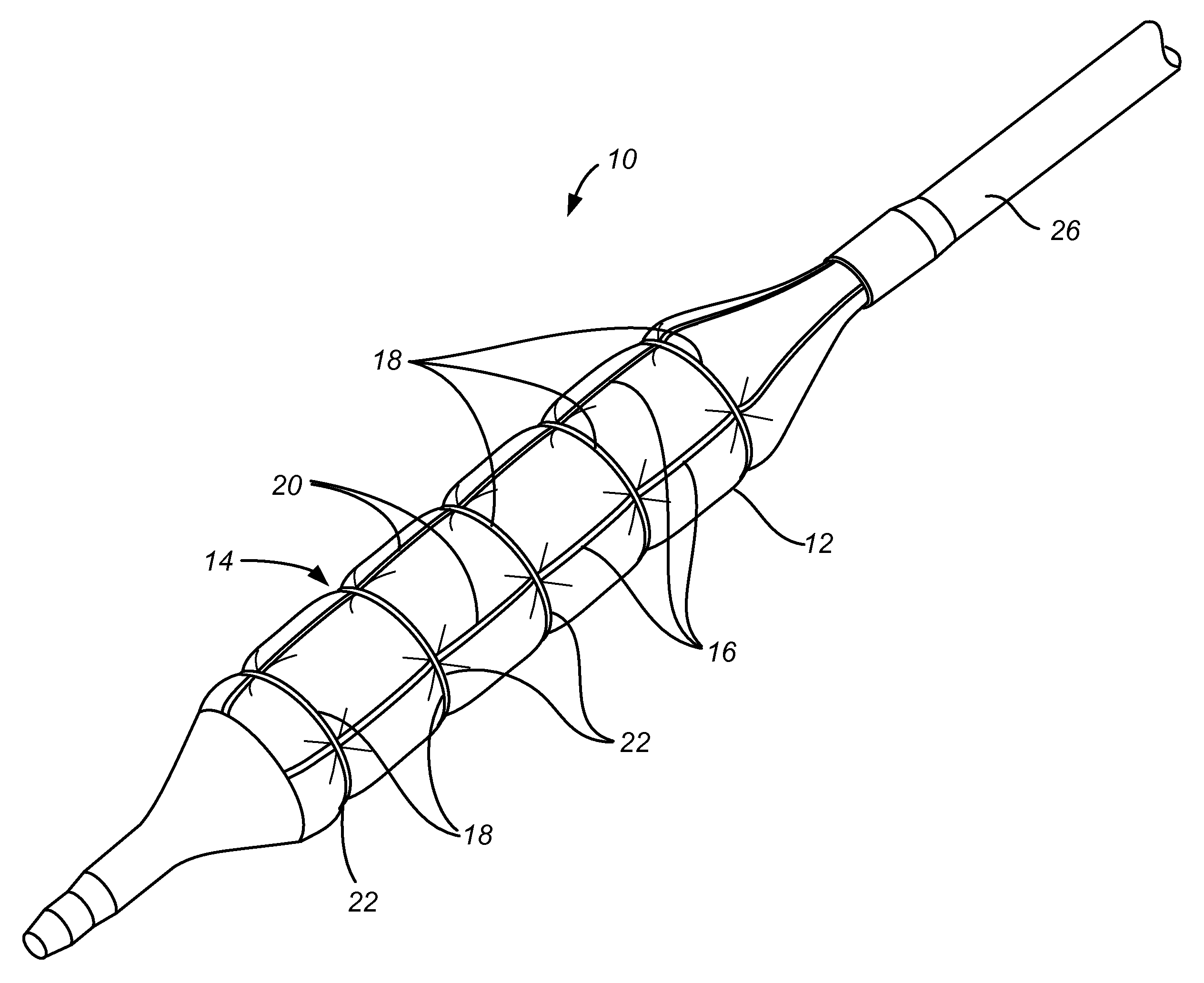
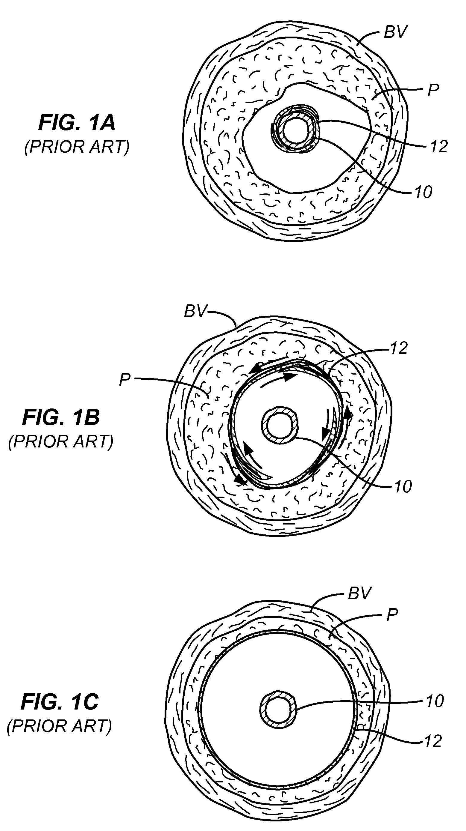
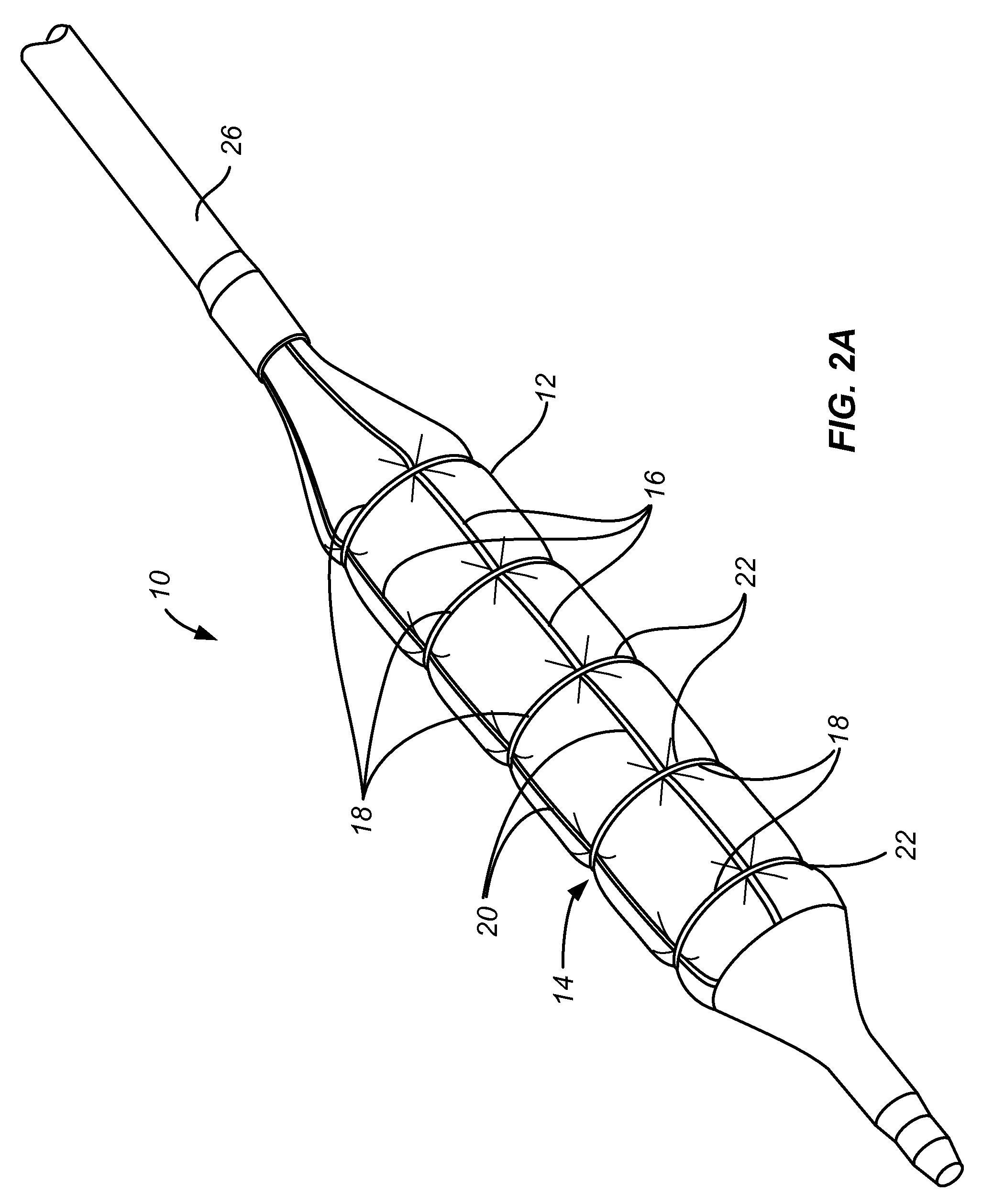
[0027]The present invention provides a device for treating of diseased, blocked, occluded or stenotic lumens in the body, typically blood vessels including both arteries and veins, and more typically coronary and peripheral arteries. This device dilates occluded vessels while minimizing trauma to the lesion and luminal wall and reducing the risk of vessel trauma and injury. By placing an “elastic” constraining structure (CS) over a balloon of a balloon catheter, inflation of the balloon is controlled during balloon inflation and refolding of the balloon is aided as the balloon is deflated. The CS is designed to expand to a diameter smaller than the maximal diameter of the balloon when fully inflated. The CS structure applies radial resistance to inflation and is thus able to constrain the balloon and distribute or buffer the internal high pressure applied by the balloon to the luminal wall thus providing a controlled and less traumatic dilation process. The balloon which is typicall...


PUM


Abstract

An angioplasty balloon having an elastic constraining structure that partially expands with the balloon so that, at maximum balloon inflation, the constraining structure forms a pattern of channels or “pillows” on the balloon.

Description

[0001]This application claims the benefit of Provisional Application No. 61 / 313,600, filed on Mar. 12, 2010, the full disclosure of which is incorporated herein by reference.BACKGROUND OF THE INVENTION[0002]1. Field of the Invention[0003]The present invention relates to the field of medical methods and devices, more specifically to medical angioplasty balloon catheters and devices intended to deliver active substances to body tissue.[0004]Angioplasty balloons are one of the most commonly used tools for the treatment of narrowed blood vessels. These balloons are typically cylindrical when inflated and have different lengths and diameters to conform to different vessel sizes. The balloons are located at the distal end of flexible catheters and delivered to a target site / lesion where they are inflated at high pressure, normally between 8-20 atmospheres, in order to overcome the resistance of the lesion and achieve luminal expansion. Such high pressure angioplasty is often associated wi...

Claims


Application Information

Patent Timeline
Patent Type & Authority Patents(United States)
IPC IPC(8): A61M29/00A61M25/10A61F2/958
CPCA61M25/104A61F2/958A61M2025/1084A61M2025/105A61B17/22A61B2017/22001A61B2017/22051
Inventor KONSTANTINO, EITANFELD, TANHUM
Owner TRIREME MEDICAL
Why Eureka
Try Eureka