
Fuel cell power system

a fuel cell and power system technology, applied in the direction of energy input, electrochemical generators, chemistry apparatuses and processes, etc., can solve the problems of inability to absorb materials that can be used, the dimensions of the hydrogen storage vessel must be increased, and the conventional power system is of little practical use in vehicles, etc., to achieve high hydrogen release temperature, large hydrogen storage capacity, and energy saving

Inactive Publication Date: 2005-05-03
HONDA MOTOR CO LTD
View PDF6 Cites 6 Cited by
  • Summary
  • Abstract
  • Description
  • Claims
  • Application Information

AI Technical Summary

Benefits of technology

[0006]It is an object of the present invention to provide a fuel cell power system that has a catalytic combustor that can provide high temperature heat as a heating means for a hydrogen storage vessel, can conserve energy by utilizing low temperature waste heat from a fuel cell as a heat source for releasing hydrogen, which is a fuel for the catalytic combustor, and can use a hydrogen absorbing material having a high hydrogen release temperature and a high hydrogen storage capacity per unit weight, and as a result is practical for use in a vehicle.
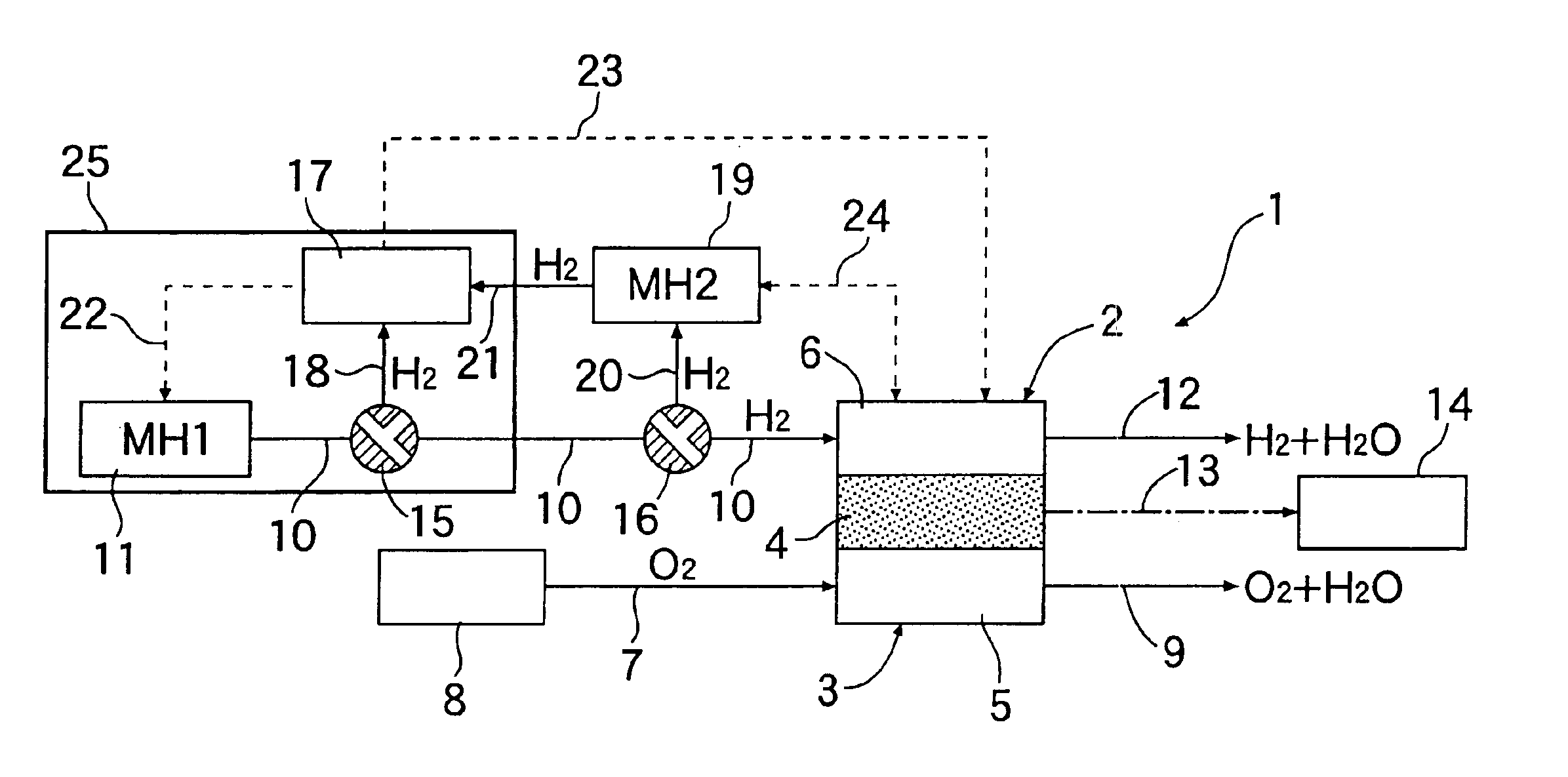
[0008]In accordance with the above-mentioned arrangement, since low temperature waste heat from the fuel cell is utilized for supplying hydrogen to the catalytic combustor, energy can be conserved. Furthermore, since the catalytic combustor can generate combustion heat up to a maximum of about 400° C. by reaction between hydrogen and air (oxygen), it is possible to utilize a hydrogen absorbing material having a large hydrogen storage capacity per unit weight and a high hydrogen release temperature that matches the combustion heat. The dimensions of the hydrogen storage vessel can thereby be reduced.

Problems solved by technology

However, the above-mentioned heating means has the problems that the hydrogen absorbing materials that can be used therein are limited to those that have a low hydrogen release temperature; since such hydrogen absorbing materials have a small hydrogen storage capacity per unit weight, the dimensions of the hydrogen storage vessel must be increased, and the conventional power systems are of little practical use in vehicles.

Method used


Image

  • Fuel cell power system
  • Fuel cell power system
  • Fuel cell power system

Examples


Embodiment Construction

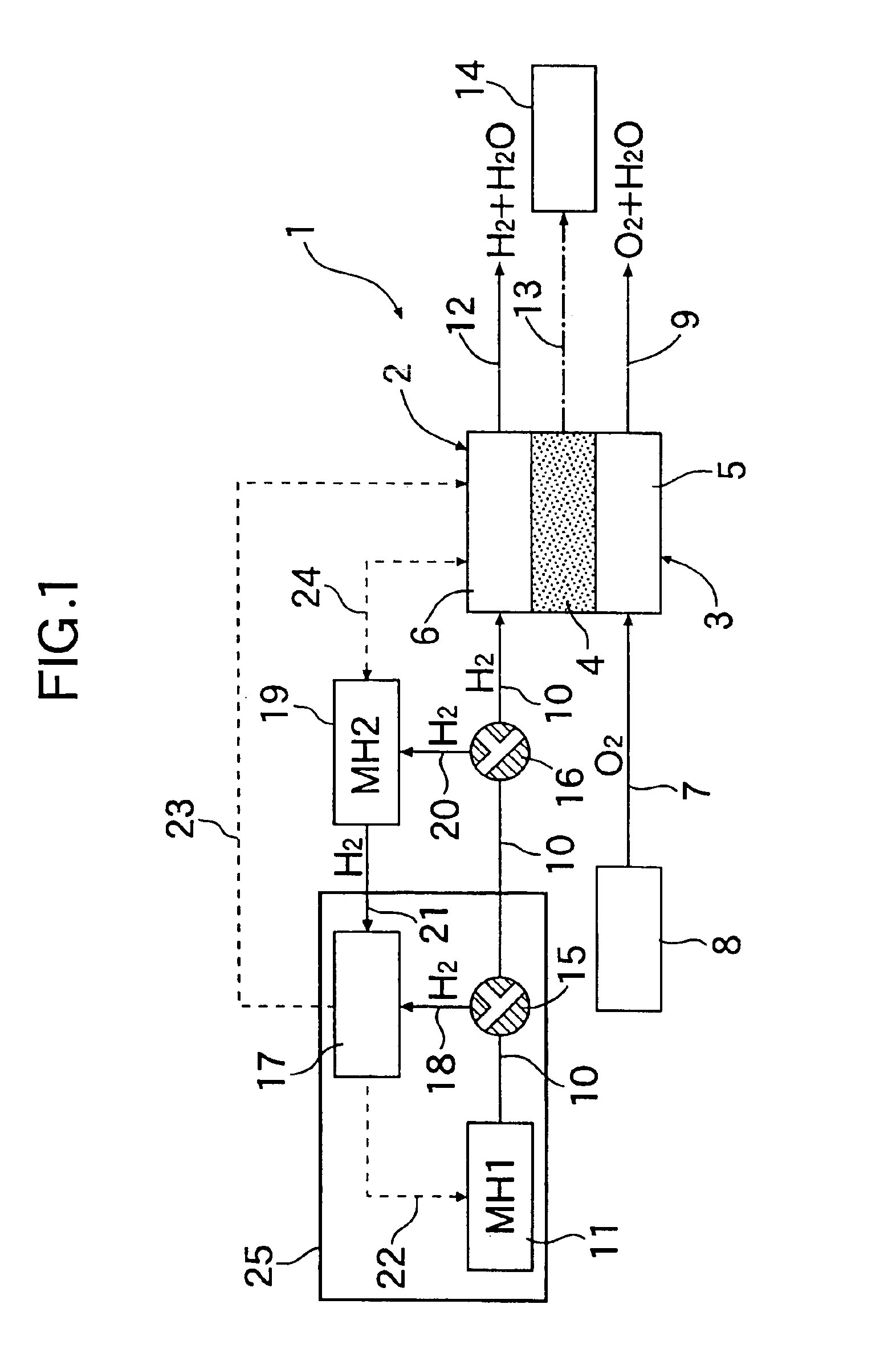
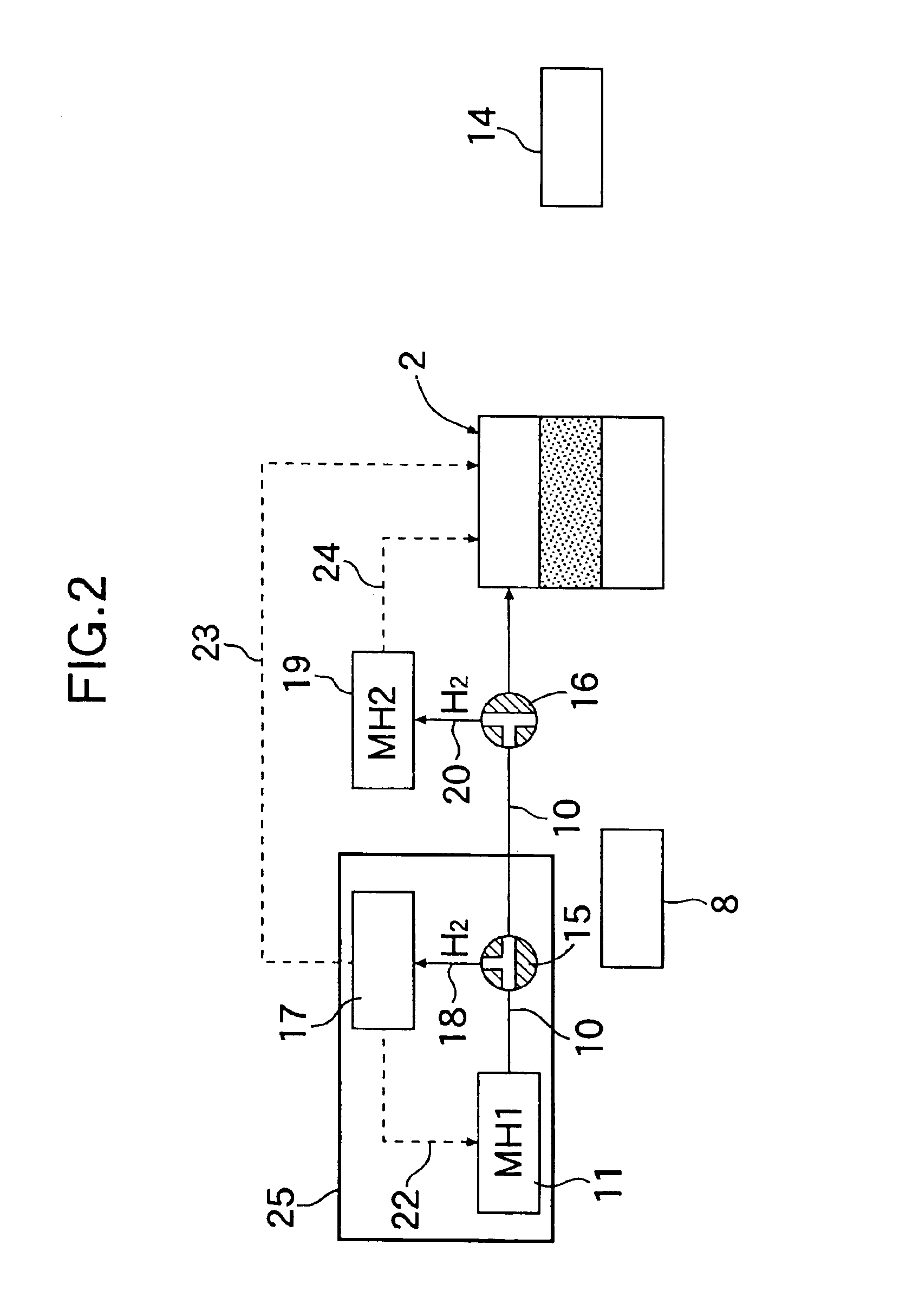
[0014]A fuel cell power system 1 shown in FIG. 1 is equipped with a solid polymer type fuel cell as a fuel cell 2, which has an operational temperature of 80° C. The fuel cell 2 has a plurality of cells 3 in a stack, and each of the cells 3 includes a solid polymer electrolyte membrane 4, an air electrode-forming part 5 and a fuel electrode-forming part 6 with the solid polymer electrolyte membrane 4 interposed therebetween. To an entrance of the air electrode-forming part 5 is connected an air supply source 8 via a pipeline 7, and to an exit thereof is connected a pipeline 9 for discharging steam and unreacted air that has not contributed to power generation. To an entrance of the fuel electrode-forming part 6 is connected a first hydrogen storage vessel 11 via a pipeline 10, and to an exit thereof is connected a pipeline 12 for discharging steam and unreacted hydrogen that has not contributed to power generation. It is arranged that the unreacted hydrogen is recycled as fuel for t...


PUM


Abstract

A fuel cell power system practical for use in a vehicle includes a fuel cell, a first hydrogen storage vessel having a first hydrogen absorbing material storing and releasing hydrogen, a catalytic combustor that heats the first hydrogen storage vessel so as to release hydrogen in order to supply hydrogen to the fuel cell, and a second hydrogen storage vessel having a second hydrogen absorbing material storing and releasing hydrogen and has a hydrogen release temperature that is lower than that of the first hydrogen absorbing material, the second hydrogen storage vessel releasing hydrogen as a fuel for the catalytic combustor under heating by waste heat from the fuel cell. Since the catalytic combustor can generate high temperature heat, a hydrogen absorbing material having a high hydrogen release temperature and a high hydrogen storage capacity per unit weight can be used as the first hydrogen absorbing material.

Description

BACKGROUND OF THE INVENTION[0001]1. Field of the Invention[0002]The present invention relates to a fuel cell power system and, in particular, to a fuel cell power system including a fuel cell and a hydrogen storage vessel having a hydrogen absorbing material that can store and release hydrogen in order to supply hydrogen to the fuel cell. Such a fuel cell power system is mounted in, for example, a vehicle.[0003]2. Description of the Related Art[0004]With regard to conventional power systems of this type, an arrangement having heating means that guides low temperature waste heat from a fuel cell to a hydrogen storage vessel by means of a blower is known (Japanese Patent Application Laid-open No. 5-47400).[0005]However, the above-mentioned heating means has the problems that the hydrogen absorbing materials that can be used therein are limited to those that have a low hydrogen release temperature; since such hydrogen absorbing materials have a small hydrogen storage capacity per unit ...

Claims


Application Information

Patent Timeline
IPC IPC(8): H01M8/04H01M8/06C01B3/00C22C23/00
CPCC01B3/0031C01B3/0042C01B3/0057C22C23/00H01M8/04014H01M8/065C22C19/03C01B2203/066Y02E60/50Y02E60/327Y02P20/129Y02E60/32
Inventor SUZUKI, TAKANORIKANOYA, IZURUHOSOE, MITSUYA
Owner HONDA MOTOR CO LTD
Learn More