Gas sample vessel for a gas analyzer

a gas analyzer and gas sample technology, applied in the shape and construction of optical resonators, withdrawing sample devices, instruments, etc., can solve the problem of point contact of mirrors with a risk of tilting before fixing could be carried out, and achieve the effect of reducing the expenditure on mirror adjustmen

Inactive Publication Date: 2005-05-03
CARL ZEISS JENA GMBH
View PDF9 Cites 4 Cited by
  • Summary
  • Abstract
  • Description
  • Claims
  • Application Information

AI Technical Summary

Benefits of technology

[0010]On this basis, it is the primary object of the invention to reduce the expenditure on adjustment of the mirrors in the manufacture of gas sample vessels of the type mentioned above.
[0013]The radius of curvature provided at the housing is preferably slightly greater than the associated radius of curvature at the mirror surfaces. In this way, an outer annular edge of the curved mirror surfaces rests on the associated housing surface, which is likewise curved, and the mirrors accordingly have a stable position relative to the housing. Conversely, if the radius of curvature of the mirror surface were greater than the associated radius of curvature at the housing, this would result in point contact of the mirror with a risk of tilting before fixing could be carried out. This should be prevented.
[0019]The first variant has proven more favorable, since mirroring the surface is less costly than producing and arranging a highly reflecting sleeve in the interior of the housing.
[0020]Further, there is a preferred variant of the arrangement according to the invention in which the illumination source is connected directly to the in-coupling mirror. This virtually prevents misalignment of the laser beam during the detection of measurement values due to shaking, for example. Further, this arrangement offers the possibility of all-purpose use at different measurement locations without readjustment of the individual elements.
[0021]For purposes of sealing and fixing the mirrors at the housing, bevels are worked in so as to form gluing gaps. By completely filling up the gluing gaps with an optical glue, the sample can be prevented from exiting the resonator cavity in an unwanted manner and can also be prevented from escaping between the mirror systems and the resonator cavity in so-called dead spaces, which could possibly corrupt the measured values.

Problems solved by technology

Conversely, if the radius of curvature of the mirror surface were greater than the associated radius of curvature at the housing, this would result in point contact of the mirror with a risk of tilting before fixing could be carried out.

Method used


Image

  • Gas sample vessel for a gas analyzer
  • Gas sample vessel for a gas analyzer
  • Gas sample vessel for a gas analyzer

Examples


Embodiment Construction

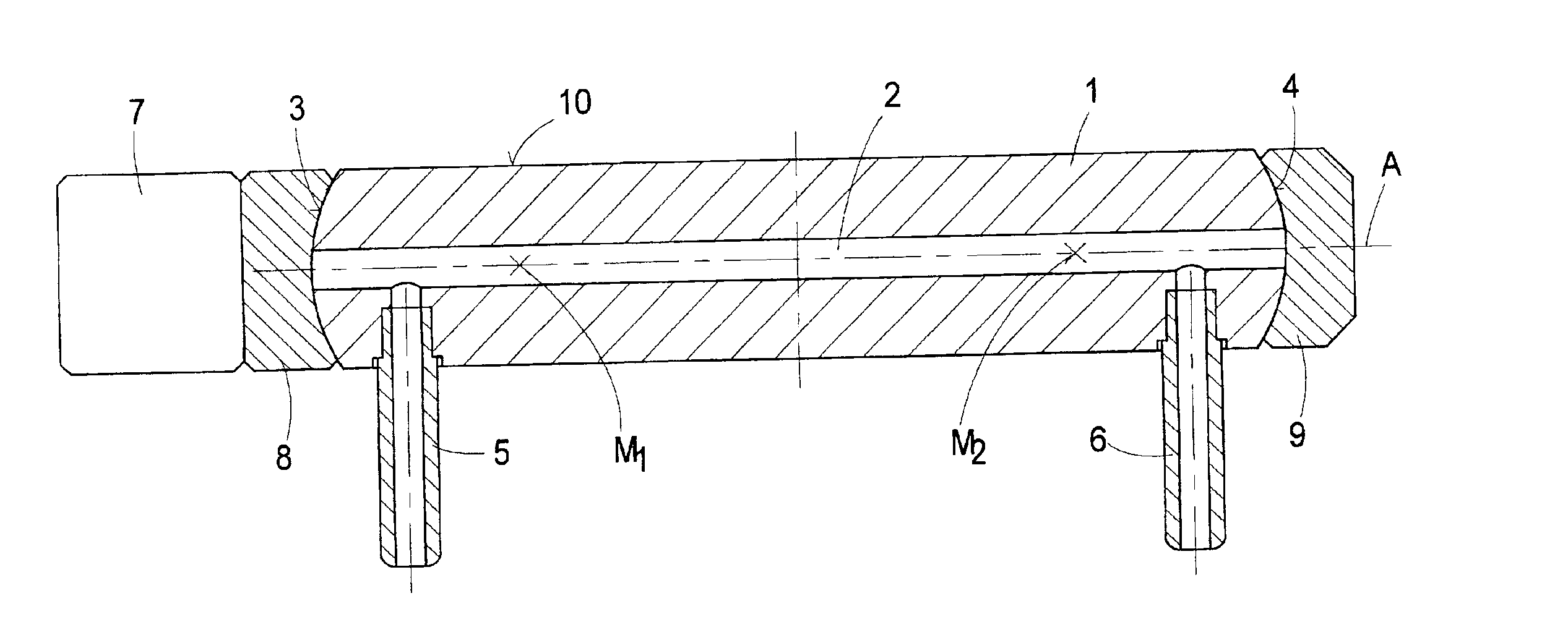
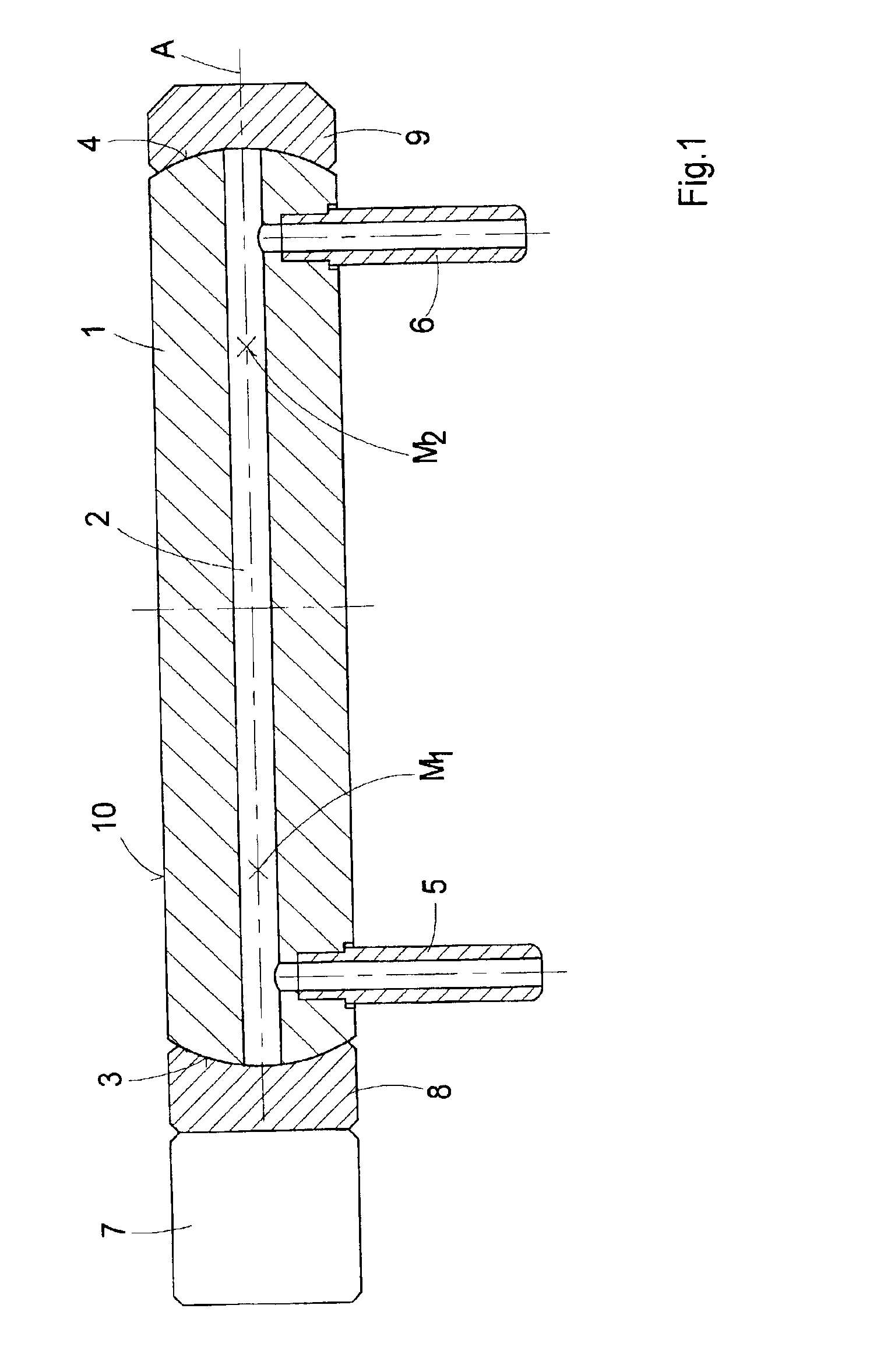
[0027]It can be seen in FIG. 1 that surfaces 3, 4 are formed at both ends of the resonator cavity 2 and are spherically curved in convex manner. The centers of curvature M1 and M2 lie in the center axis A.

[0028]A gas inlet connection piece 5 and a gas outlet connection piece 6 are fixedly arranged in the housing 1 vertical to the center axis A.

[0029]Mirrors 8 and 9 are arranged at the surfaces 3, 4 of the housing 1 so that the measurement light beam proceeding from a laser 7 can enter the resonator cavity and so that the radiation can be fed back. In this case, for example, the mirror 8 is connected directly to the laser 7.

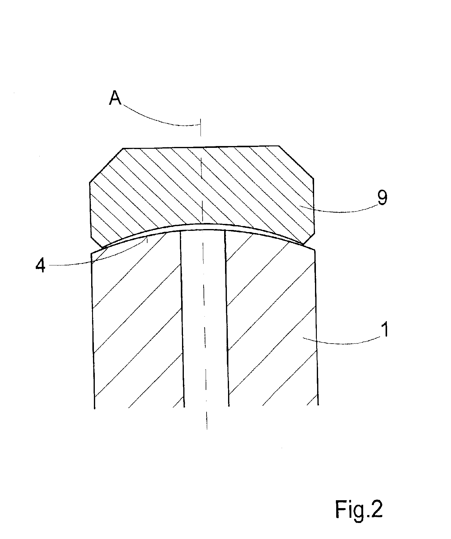
[0030]The surfaces of the mirrors 8, 9 facing the housing 1 are likewise spherical, but are curved concavely. The radii of curvature of the mirrors 8, 9 are preferably somewhat smaller than the radii of curvature of the surfaces 3, 4, resulting in the contact of a curved mirror surface at the housing surface, which is likewise curved, as is shown in the enlarged v...


PUM

PropertyMeasurementUnit
radius of curvatureaaaaaaaaaa
radii of curvatureaaaaaaaaaa
areaaaaaaaaaaa

Abstract

A gas sample vessel for a gas analyzer comprising a housing enclosing a cylindrical resonator cavity. Two mirrors which limit the resonator cavity are fastened to the housing for coupling in and feeding back the measurement light proceeding from an illumination source. The mirrors are curved concavely at their surfaces facing the housing and the housing is curved convexly at its surfaces facing the mirrors with approximately the same radius of curvature. The centers of curvature lie in the center axis of the resonator cavity and the mirror surfaces of the mirrors are portions of the concavely curved surfaces facing the housing.

Description

CROSS-REFERENCE TO RELATED APPLICATIONS[0001]This application claims priority of German Application No. 101 57 275, filed Nov. 22, 2001, the complete disclosure of which is hereby incorporated by reference.BACKGROUND OF THE INVENTION[0002]a) Field Invention of the Invention[0003]The invention is directed to a gas sample vessel for a gas analyzer comprising a housing enclosing a cylindrical resonator cavity, two mirrors which limit the resonator cavity being fastened to the housing for coupling in and feeding back the measurement light proceeding from an illumination source.[0004]b) Description of the Related Art[0005]Measuring devices known as gas analyzers are used to determine the properties of a gas. Gas analyzers frequently have a cavity resonator, as it is called, which receives a gas sample and into which a light beam is coupled in a defined manner. The propagation of the light within the cavity is influenced depending on the properties of the gas. This influence is evaluated ...

Claims


Application Information

Patent Timeline
Patent Type & Authority Patents(United States)
IPC IPC(8): G01N21/05G01N21/03G01N21/61H01S3/08
CPCG01N21/05G01N21/031
Inventor KERSTAN, FELIXHOYME, WERNERCORRENS, NICOKLARNER, ULLRICH
Owner CARL ZEISS JENA GMBH
Why Eureka
Try Eureka