Reflector telescope

a reflector telescope and telescope technology, applied in the field of reflector telescopes, can solve the problems of difficult and expensive manufacture of paraboloidal mirrors, telescopes unsuitable for photography, and use of paraboloidal mirrors in reflector telescopes, and achieve the effect of reducing or substantially eliminating spherical aberration and generally flat field of view

Inactive Publication Date: 2005-05-03
NEWISE TECH LTD
View PDF16 Cites 5 Cited by
  • Summary
  • Abstract
  • Description
  • Claims
  • Application Information

AI Technical Summary

Benefits of technology

[0009]It is an object of the present invention, therefore, to provide a reflector telescope which employs a spherical primary reflector but which reduces or substantially eliminates spherical aberration whilst being both compact and relatively inexpensive to produce. It is a further object of the invention to provide a reflecting telescope which is diffraction limited and which produces a generally flat field of view.

Problems solved by technology

However, the use of paraboloidal mirrors in reflector telescopes does have certain disadvantages.
Firstly, the image is strongly distorted towards the edge of the field of view—an aberration of the reflector known as coma in which the image of a point lying off the axis of the reflector has a comet-shaped appearance—making such telescopes unsuitable for photography.
In addition, the manufacture of paraboloidal mirrors is difficult and expensive.
However, the use of spherical primary reflectors in reflecting telescopes also presents a number of disadvantages.
While coma distortion is not present, spherical mirrors suffer from a defect known as spherical aberration in which the rays of light incident on the mirror come to a focus in slightly different positions rather than a common focal point.
Naturally, this results in manufacturing difficulties and increased expense.
Moreover, spherical aberration varies inversely with the cube of the focal length of the mirror so that, again, the manufacture of compact telescopes is extremely difficult.
These instruments also normally have a very large central obstruction, which degrades the image by transferring some of the energy in the Airey disc to the diffraction rings.
Maksutov and Schmidt / Cassegrain telescopes also have a third reflection normally through a hole in the primary mirror and thus have an inconvenient observing position.

Method used


Image

  • Reflector telescope
  • Reflector telescope
  • Reflector telescope

Examples


Embodiment Construction

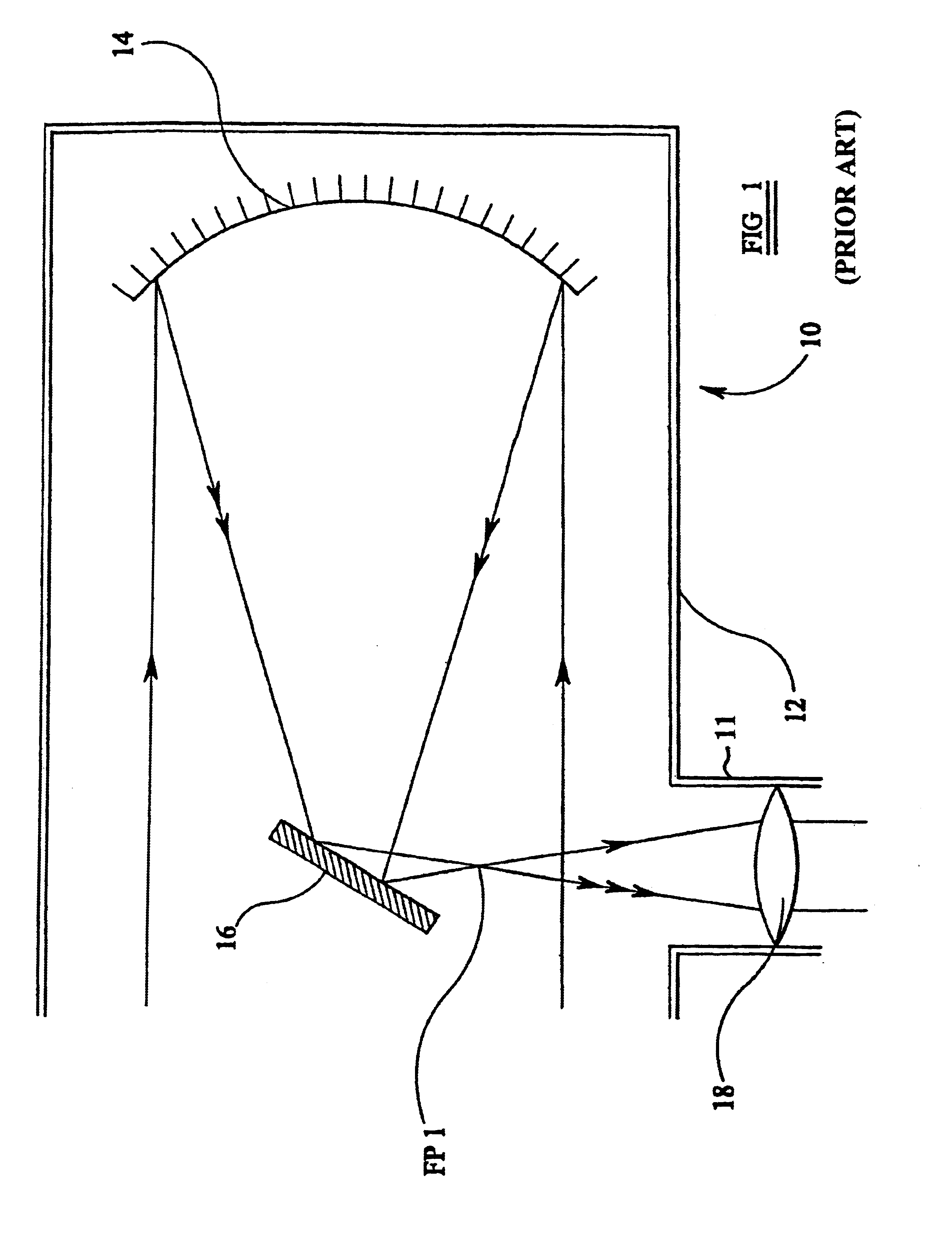
[0024]In FIG. 1, a simplified diagram of a conventional Newtonian reflecting telescope is shown generally at 10. The telescope consists of a generally elongate, cylindrical tube 12, open at one end thereof (or otherwise provided with an optical window) to allow the passage of light rays from a distant object into the telescope. A primary reflector in the form of a concave mirror 14, usually paraboloidal in shape, is mounted at the other end of the tube with its reflective surface directed towards the open end or optical window.

[0025]A secondary reflector in the form of a generally planar mirror 16 is mounted within the tube at a position between the open end of the tube and the primary reflector 14 with its reflective surface directed generally towards the primary reflector 14 but angled at 45° away from the central axis CA of the primary reflector 14. A lens 18 is mounted coaxially within a tube 11 arranged substantially at right-angles to the main tube 12 and serves as an ocular o...


PUM


Abstract

A compact reflector telescope has a spherical primary reflector and a secondary reflector with a negative lens interposed there between in axial alignment therewith. Light reflected from the primary reflector is passed through the negative lens and is diverted by the secondary reflector to a positive lens at the side of the telescope tube. The positive lens focuses the light rays onto an eye piece or ocular or onto a photographic emulsion or electronic detector. The telescope reduces or substantially eliminates spherical aberration and can be configured to have a focal ratio significantly greater than the focal ratio of the primary reflector. The telescope produces a flat field of view and an image which is substantially diffraction limited.

Description

BACKGROUND[0001]1. Field of the Invention[0002]The present invention relates to a reflector telescope and particularly, to a catadioptric reflector telescope employing a spherical primary reflector having a relatively short focal length and which reduces or substantially eliminates the problems conventionally associated with the use of spherical mirrors in reflector telescopes.[0003]2. Description of the Prior Art[0004]Reflector telescopes generally employ a concave primary reflector which collects and focuses light incident upon the reflector surface through the telescope's aperture and a smaller secondary reflector to direct the reflected light to the telescope's eyepiece. Normally, the primary reflector is provided by a paraboloidal mirror which has certain advantages in terms of imaging, the most important being that all parallel rays of light incident on the mirror are convergent at the focal point of the mirror, irrespective of the distance of the point of incidence from the c...

Claims


Application Information

Patent Timeline
Patent Type & Authority Patents(United States)
IPC IPC(8): G02B17/08G02B23/02G02B23/06
CPCG02B17/08G02B23/06G02B17/0852
Inventor WISE, PETER
Owner NEWISE TECH LTD
Why Eureka
Try Eureka