
Optical configuration for a compact integrated day/night viewing and laser range finding system

a laser range finding and integrated technology, applied in the direction of distance measurement, instruments, using reradiation, etc., can solve the problems of inability to achieve laser range finding, system weight too large to be operational effective, and inability to achieve hand held jitter, etc., to achieve the effect of reducing the size and weight of optical systems, eliminating dichroic beam splitter, and compact packag

Active Publication Date: 2015-09-10
RAYTHEON CO
View PDF1 Cites 6 Cited by
  • Summary
  • Abstract
  • Description
  • Claims
  • Application Information

AI Technical Summary

Benefits of technology

The patent describes an optical configuration that reduces the size and weight of optical systems used in laser range-finders and other applications. This is achieved by eliminating a dichroic beamsplitter, which is a large and heavy component in current configurations. The new solution allows for direct view blocking and enables laser range-finding during viewing of the display. This results in a more compact and efficient optical configuration.

Problems solved by technology

Conventional handheld optical systems that contain a direct view optical path along with night viewing and laser range finding capability suffer from several drawbacks and disadvantages.
These systems are heavy due to the number of components needed to support multiple apertures and the use of exclusively refractive optical components, and suffer from boresight retention problems which result in range finding errors.
In particular, such systems tend to be too heavy to be operational effective especially when locating relatively small targets, the weight inducing unacceptable hand held jitter.
U.S. Pat. No. 6,020,994 to Cook discloses a common aperture solution; however, this system is not scalable in terms of magnification.
In addition, in conventional common aperture solutions, additional beamsplitter(s) and blocking mirror / plate (typically positioned at a 45° angle) required to allow the optical paths to share the common aperture force the package width or height to an unacceptable size for many handheld applications.
In some larger aperture systems that are not handheld, where large refractive components would make the system expensive and heavy, reflective telescope assemblies have been incorporated to replace the refractive components.
However, implementing light weight reflective technology into handheld optical systems has not been accomplished.

Method used


Image

  • Optical configuration for a compact integrated day/night viewing and laser range finding system
  • Optical configuration for a compact integrated day/night viewing and laser range finding system
  • Optical configuration for a compact integrated day/night viewing and laser range finding system

Examples


Embodiment Construction

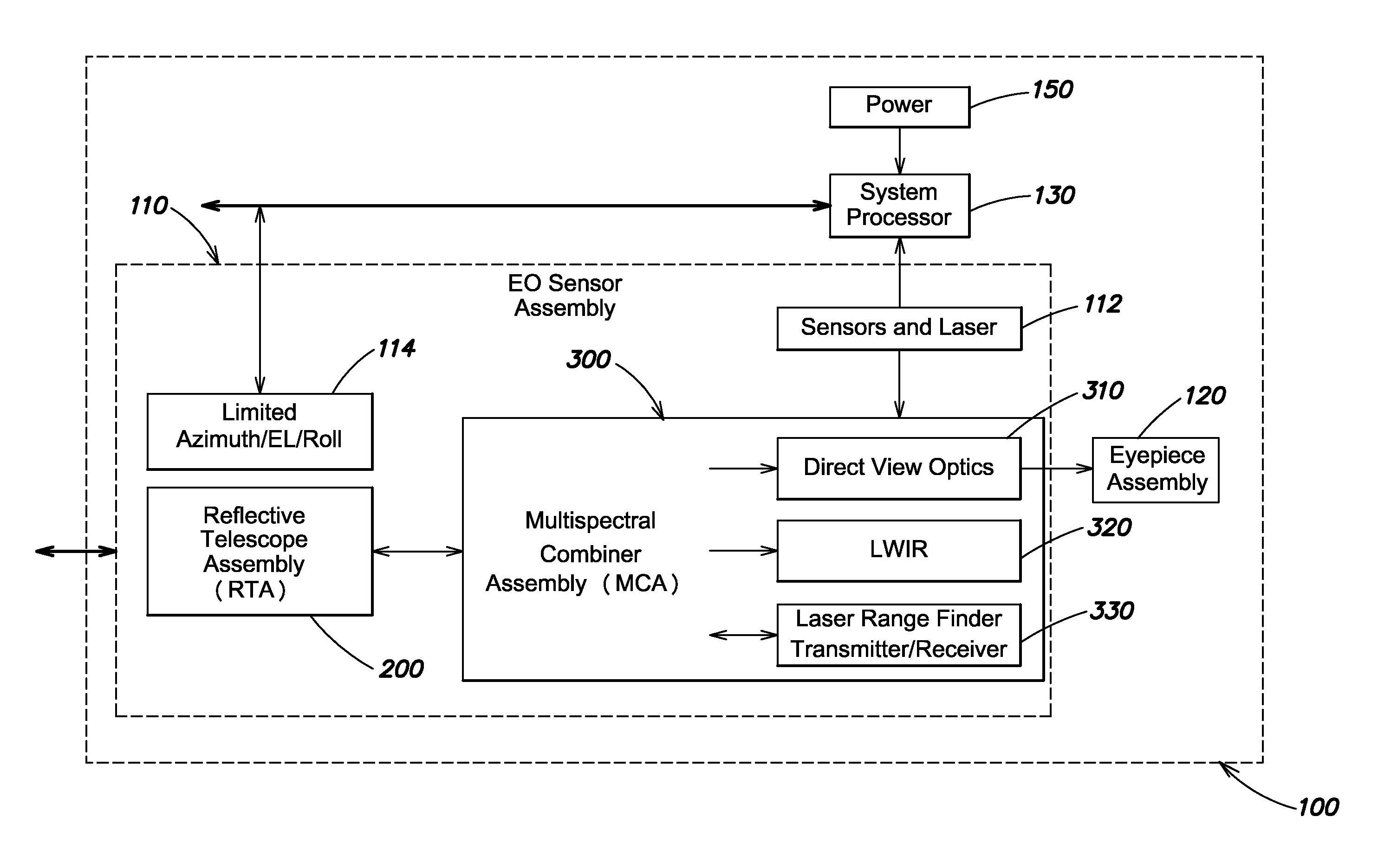
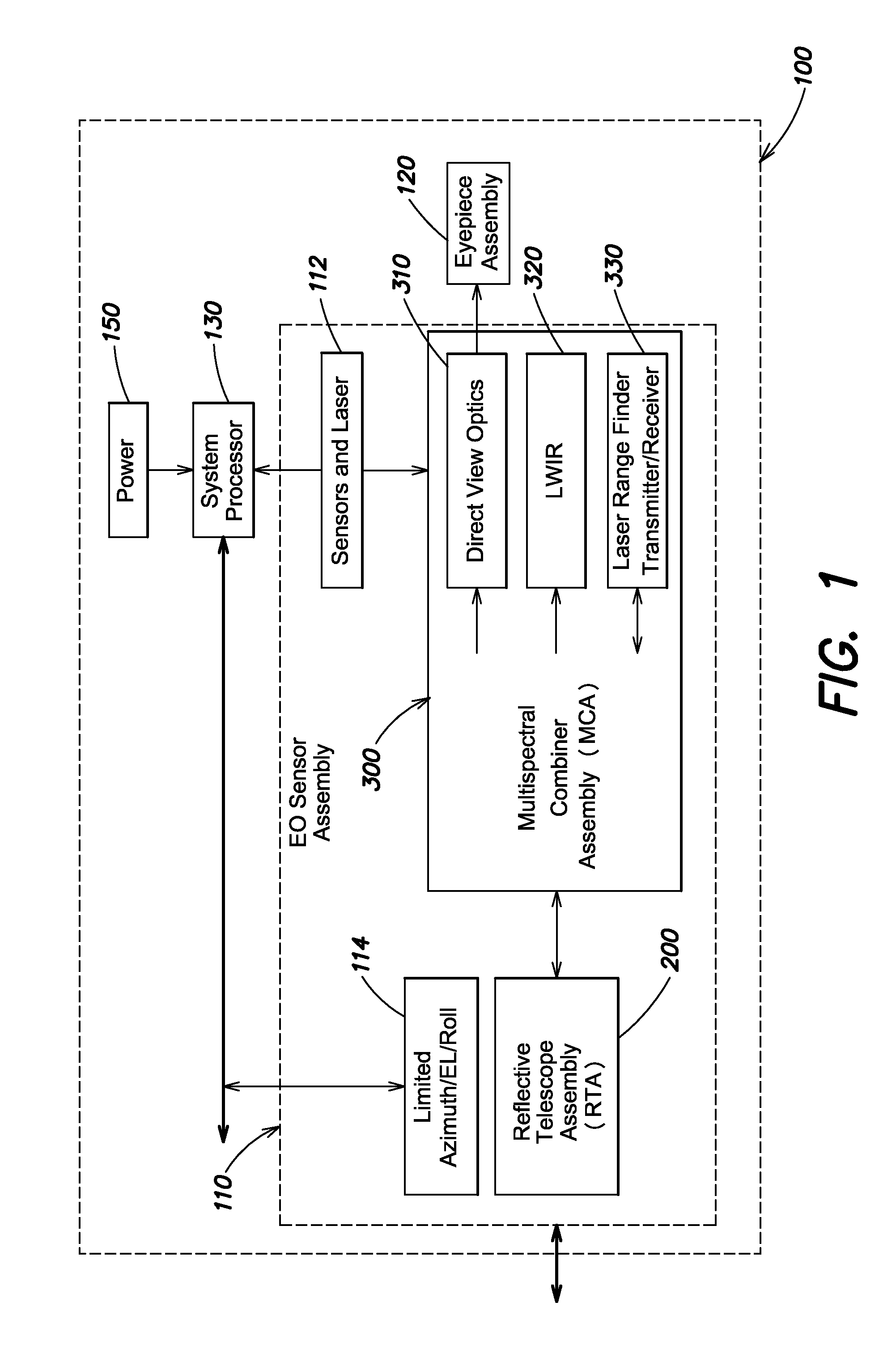
[0015]Aspects and embodiments are directed to an optical configuration for an optical system that incorporates both day viewing (referred to as a direct view optical path) and night viewing (also referred to an infrared optical path or thermal imaging) capability, as well as an integrated laser range-finder. Such an optical system may be used in a variety of devices including, for example, target location systems, rifle scopes, multispectral viewing or imaging systems, and the like. In particular, aspects and embodiments of the optical system discussed herein may be advantageously used in devices where size and weight are of significant concern, including, for example, handheld target location systems. Certain of these devices or systems include an eyepiece that allows a user to directly view a scene through the eyepiece, as well as a display that displays processed infrared imagery to enable night-viewing capability.

[0016]The conventional state of the art configuration for such a h...


PUM


Abstract

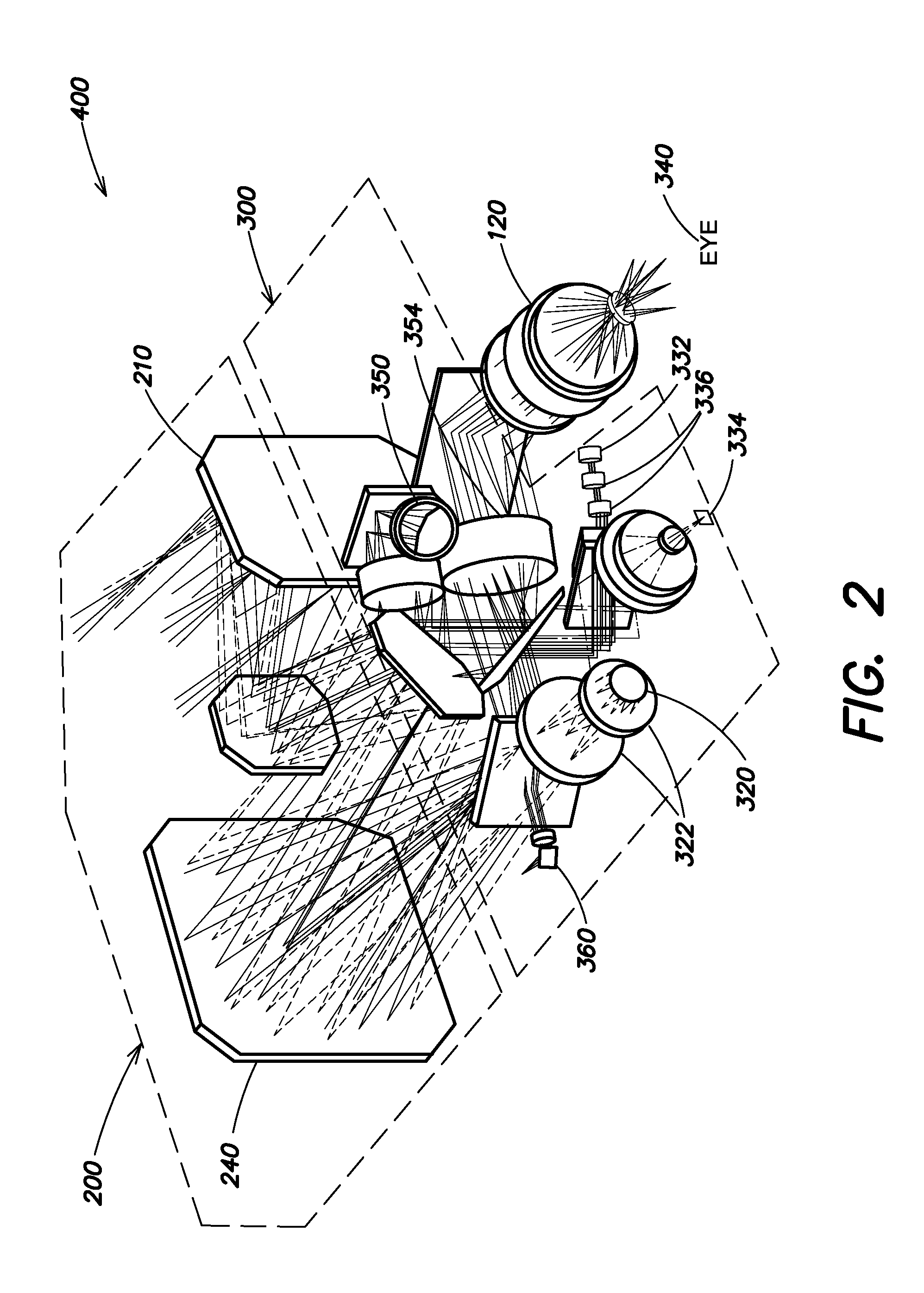
A compact integrated optical system including an eyepiece, a reflective telescope, and a multi-spectral combiner optically coupled between the reflective telescope and the eyepiece, and configured to direct visible light received via the reflective telescope assembly along a direct view optical path to the eyepiece assembly. In one example, the multi-spectral combiner includes a display that displays a visual representation of the imagery of the viewed scene, and laser range-finder transceiver that transmits and receives a laser beam via the reflective telescope. A pair of beamsplitters is used to separate the imaging optical path from the direct view and laser range-finding optical paths. A blocking device is used to enable laser range-finding capability during daytime viewing of the imaging optical path imagery on the display. The reflective telescope provides a common aperture for the direct view optical path, an imaging optical path, and the laser range-finder transceiver.

Description

BACKGROUND[0001]Conventional handheld optical systems that contain a direct view optical path along with night viewing and laser range finding capability suffer from several drawbacks and disadvantages. Most currently fielded military handheld devices are multiple aperture systems utilizing refractive or glass components. These systems are heavy due to the number of components needed to support multiple apertures and the use of exclusively refractive optical components, and suffer from boresight retention problems which result in range finding errors. In particular, such systems tend to be too heavy to be operational effective especially when locating relatively small targets, the weight inducing unacceptable hand held jitter. U.S. Pat. No. 6,020,994 to Cook discloses a common aperture solution; however, this system is not scalable in terms of magnification. In addition, in conventional common aperture solutions, additional beamsplitter(s) and blocking mirror / plate (typically positi...

Claims


Application Information

Patent Timeline
IPC IPC(8): G01C3/04G02B23/04G01S17/86
CPCG02B23/04G01C3/04G02B13/146G02B23/10G02B27/141F41G1/32G01S17/08G01S7/4812F41G3/065F41G3/165G01S17/86
Inventor SISNEY, BRENT L.CHIPPER, ROBERT B.JACKSON, JOHN
Owner RAYTHEON CO
Learn More