
Optical calibration device for reflecting telescope optical axis monitoring based on polarization and beam splitting

A polarization beam splitting prism and polarization beam splitting technology, applied in optical axis determination, lens position determination, optical and other directions, can solve the problems of difficult to give accurate optical axis pointing, low precision, dependence, etc., and achieve high test repeatability and high accuracy Precision optical axis registration, the effect of eliminating reading errors

Pending Publication Date: 2020-02-14
SHANGHAI INST OF TECHNICAL PHYSICS - CHINESE ACAD OF SCI
View PDF0 Cites 6 Cited by
  • Summary
  • Abstract
  • Description
  • Claims
  • Application Information

AI Technical Summary

Problems solved by technology

There are two traditional schemes: first, during the processing of the primary mirror of the telescope, the perpendicularity between the optical axis of the primary mirror and the back of the primary mirror is strictly controlled, and the normal line of the back of the primary mirror is adjusted when optically calibrating the reflective telescope system. It is collinear with the normal line of the auxiliary large-aperture plane mirror as the optical axis registration. This method depends on processing and has low precision, and it is difficult to give accurate optical axis orientation
The second method is to use the theodolite to align the optical axis of the telescope system, then rotate the theodolite 180°, and adjust the auxiliary large-caliber standard plane mirror so that the normal line coincides with the optical axis of the theodolite, so that establishing a benchmark will introduce various errors, and the fixation of the theodolite Error, the zero position error of adjusting the theodolite level, the rotation error introduced by the rotating theodolite, etc., the process is cumbersome, the repeatability is not high, and it is difficult to realize the real-time monitoring of the optical axis during the optical calibration process

Method used


Image

  • Optical calibration device for reflecting telescope optical axis monitoring based on polarization and beam splitting
  • Optical calibration device for reflecting telescope optical axis monitoring based on polarization and beam splitting
  • Optical calibration device for reflecting telescope optical axis monitoring based on polarization and beam splitting

Examples


Embodiment Construction

[0015] The implementation examples of the patented method will be described in detail below in conjunction with the accompanying drawings.

[0016] The main components used in the present invention are described:

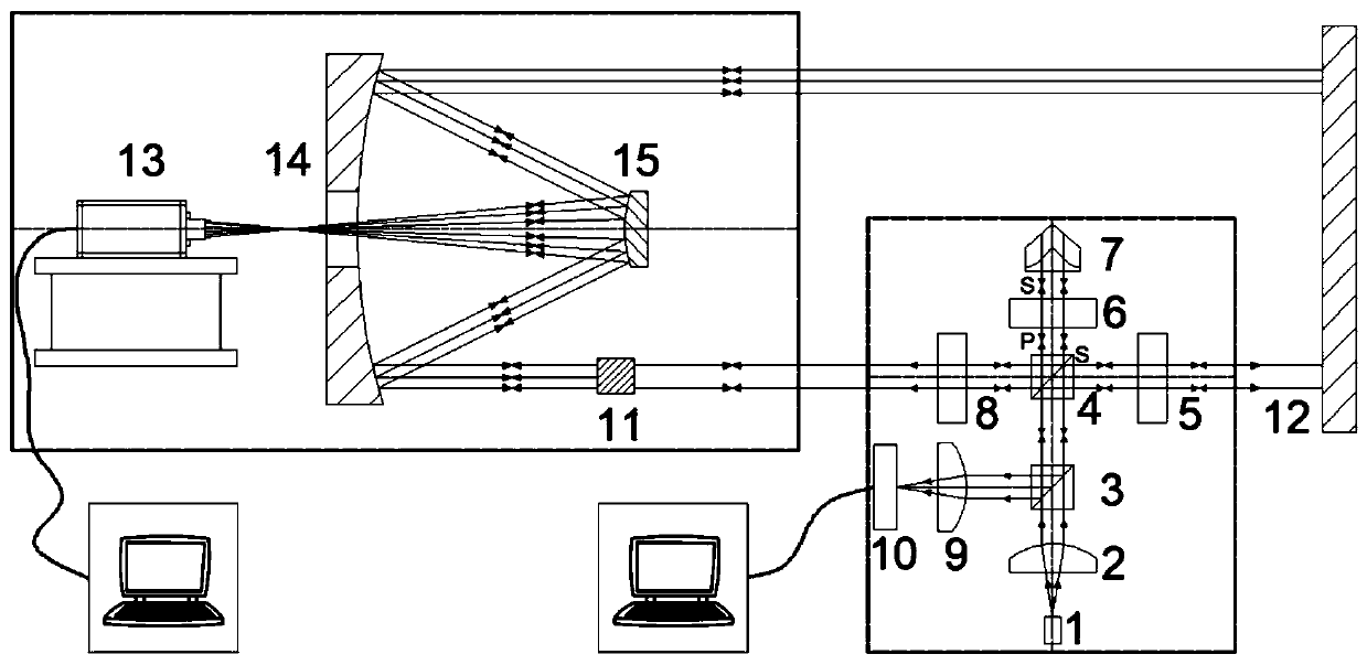
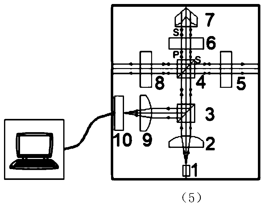
[0017] Fiber optic light source 1: Coupling the laser with a wavelength of 633nm to a single-mode fiber with a core diameter of 10um for output.

[0018] Collimator lens 2: sample Edmund's model #36-165 molded aspheric lens, diameter 12.5mm, focal length 10mm.

[0019] Beam-splitting prism 3: sample Thorlab's model BS016 beam-splitting cube with an aperture of 20mm, made of quartz, a quarter wavelength of the transmitted wavefront@633nm, and a beam-splitting ratio of 50:50.

[0020] Polarization beam splitter 4: sampling Thorlab's model is PBS202, a polarization beam splitter cube with an aperture of 20mm, material SF1, a quarter wavelength of the transmitted wavefront @633nm, and a polarization beam splitting ratio of 1000:1.

[0021] No. 1 parallel plate 5, No. ...


PUM


Abstract

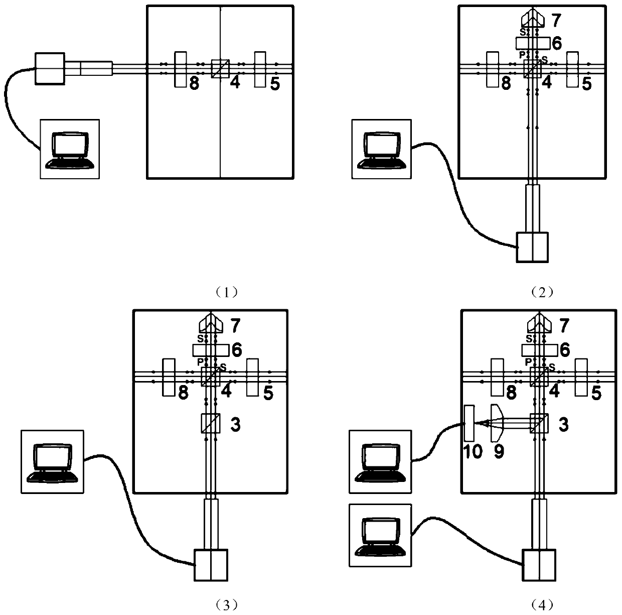
The invention discloses an optical calibration device for reflecting telescope optical axis monitoring based on polarization and beam splitting. The device comprises an optical fiber light source, a collimating lens, a beam splitting prism, a polarization and beam splitting prism, a first parallel flat plate, a quarter-wave plate, a pyramid prism, a second parallel flat plate, a converging lens and a detector. In the optical calibration process of a telescope system, the polarization and beam splitting prism, the quarter-wave plate and the pyramid prism are adopted to generate two beams whichare collinear in opposite directions, and high-precision registration of the optical axis of the optically calibrated telescope system and the normal of an auxiliary standard plane mirror is realized.The device is used for a relative test and overcomes test precision problems brought by manual interpretation errors, a test environment and the like in a traditional optical axis absolute test. Besides, the reference optical axis and the test optical axis share the same optical path, the influence of vibration in the testing process is avoided, and therefore test efficiency and optical calibration efficiency are greatly improved.

Description

technical field [0001] The invention belongs to the field of optical testing and optical adjustment, and relates to an optical calibration device for monitoring the optical axis of a reflective telescope based on polarization splitting, and is especially suitable for optical calibration of a reflective telescope system. Registration and real-time monitoring of plane mirror normals. It is also suitable for large-diameter aspheric mirror processing, laser emission and reception registration and other fields. Background technique [0002] Reflective space optical camera loads such as laser radar and laser altimeter have higher and higher requirements for the optical axis pointing of the reflective telescope system in the optical load. Point-to-point testing requires higher and higher registration accuracy. In the optical assembly process, the most important thing is to collinearly register the optical axis of the space reflective telescope system to be optically corrected and...

Claims


Application Information

Patent Timeline
IPC IPC(8): G01M11/02G02B27/30
CPCG01M11/0221G02B27/30
Inventor 刘强王欣黄庚华何志平舒嵘
Owner SHANGHAI INST OF TECHNICAL PHYSICS - CHINESE ACAD OF SCI
Learn More