
Dynamically adjustable digital gyrator having extendable feedback for stable DC load line

a dynamic adjustable, dc load technology, applied in the field of digital gyrator methods and apparatus, can solve the problems of less than optimal circuit of fig. 16, limited physical components, and adjustability of circuits, and achieve the effect of reducing the detected oscillation

Inactive Publication Date: 2005-05-03
AGERE SYST GUARDIAN
View PDF9 Cites 24 Cited by
  • Summary
  • Abstract
  • Description
  • Claims
  • Application Information

AI Technical Summary

Benefits of technology

The digital gyrator provides stable and adaptable DC current emulation, allowing for quick connection establishment and compliance with various country-specific requirements without the need for physical component changes, reducing costs and improving flexibility.

Problems solved by technology

The circuit of FIG. 16 is less than optimal because of the inherently bulky nature and high cost of the inductor L, the amount of time for inductor L to charge, and the need to change circuit elements in countries with different off-hook current level requirements.
However, the adjustability of the circuit is set when the circuit is manufactured, limited by the physical components used in the circuit.
This low corner frequency comes at the price of slow settling time.
Thus, conventional DC current levels are set using external components on a country by country basis, resulting in an expensive and inflexible solution.
However, the digital transport delay between a digital signal processor (DSP) and its host processor will vary, e.g., because of bus delay, etc.
These transport delays may introduce enough phase delay such that it may not be possible to find one lowpass filter cutoff frequency to make the gyrator stable on all possible central office line terminations.
If the gyrator is not stable, the modem will not be able to establish a connection.

Method used


Image

  • Dynamically adjustable digital gyrator having extendable feedback for stable DC load line
  • Dynamically adjustable digital gyrator having extendable feedback for stable DC load line
  • Dynamically adjustable digital gyrator having extendable feedback for stable DC load line

Examples


Embodiment Construction

[0043]One example of a digital gyrator forming a basis for the present invention is described in U.S. applicaton Ser. No. 09 / 310,021, entitled “Digital Gyrator” filed May 11, 1999 by Jonathan H. Fischer, Donald R. Laturell, and Lane A. Smith, the entirety of which is expressly incorporated herein by reference.

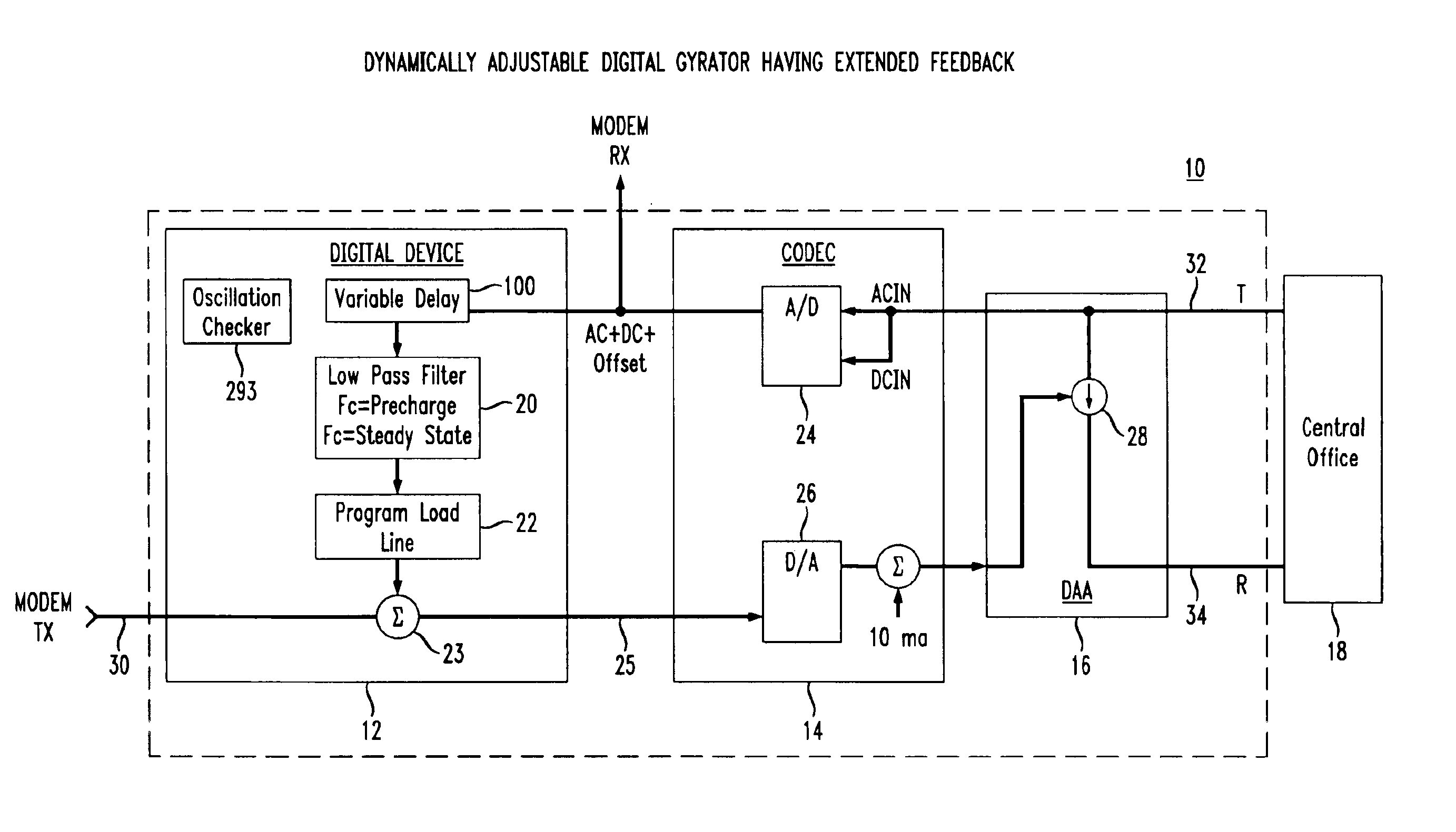
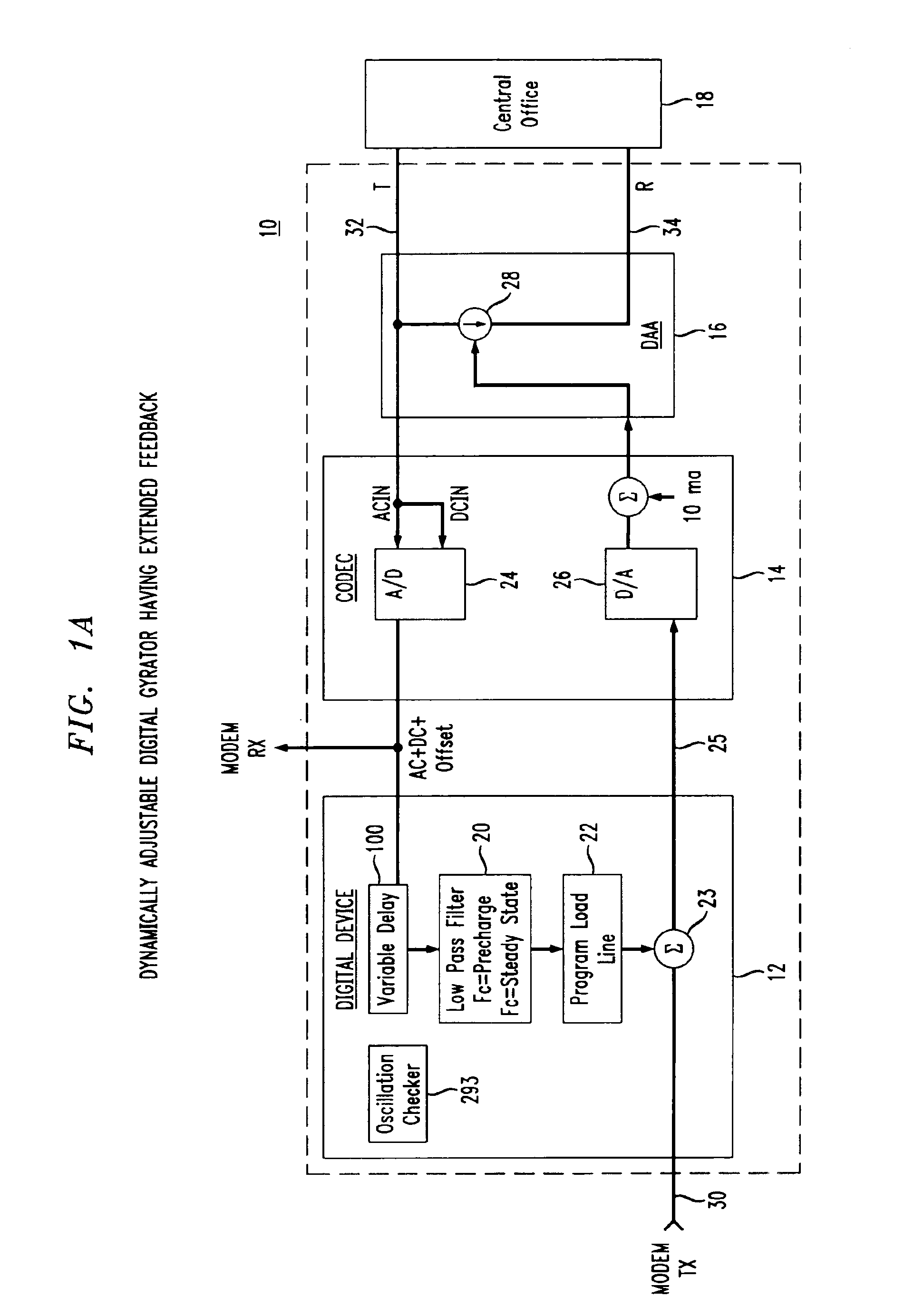
[0044]The present invention relates to the implementation of a dynamically adjustable digital gyrator for a telephone line interface (e.g., a DAA) to emulate the large inductor typically seen in conventional telephone sets. In accordance with the principles of the present invention, the large inductor is emulated by a low pass filter having adjustable cutoff frequencies which are changed according to whether or not an off-hook oscillation is detected. The low pass filter preferably operates at the modem sample rate.

[0045]The digital transport delay (i.e., a delay from a digital signal processor (DSP) to a processor on the modem's host device) varies from system to system. In so...


PUM


Abstract

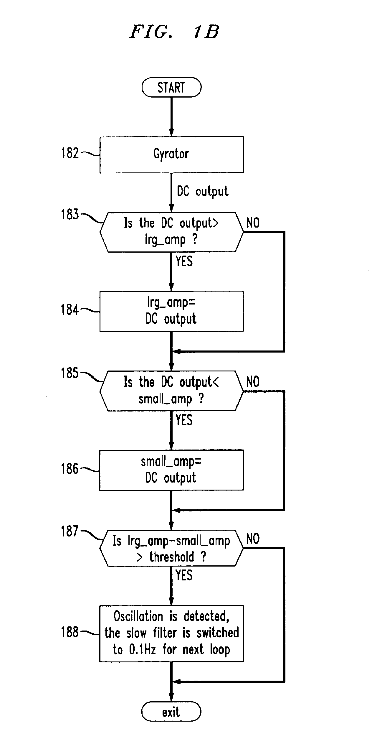
A dynamically adjustable digital gyrator device for a telephone line interface (e.g., a DAA) utilizing extended feedback and a dynamically adjustable filter to achieve stable convergence in the control of DC line current on a telephone line a short period of time. The low pass filter of the digital gyrator includes at least two (2) different fast filter settings and at least two (2) different slow filter settings based on possible load terminations (e.g., PBX, TAS, etc.), which can be determined based on the dynamic detection of an oscillation on the line. For instance, in a disclosed example, a voice band modem system is allowed to go off-hook with a 1 Hz cutoff low pass filter, and then the output of the low pass filter is checked for an oscillation. If an oscillation is detected, then the poles and / or zeroes of the low pass filter cutoff are changed to a slower convergence rate cutoff frequency (e.g., to 0.1 Hz). As a result, the exemplary voice band modem will converge stably and quickly (e.g., in less than 1 second) before dialing begins. By controlling the DC line current digitally, software can be used to set the DC line current in accordance with predefined characteristics. Predefined characteristics can be set to accommodate varying country specifications instead of using switches to control resistors and capacitors.

Description

[0001]This is a continuation of Ser. No. 09 / 310,021 filed on May 11, 1999 now U.S. Pat. No. 6,665,403.BACKGROUND OF THE INVENTION[0002]1. Field of the Invention[0003]This invention relates generally to a DAA interface (e.g., a Data Access Arrangement for a modem, telephone answering device, etc.) More particularly, it relates to a digital gyrator method and apparatus which emulates an inductor value of a telephone line interface on a telephone line in a stable manner after going into an off-hook condition.[0004]2. Background of Related Art[0005]Telephone systems in countries throughout the world have unique system requirements that need to be followed in order to legally sell and use telecommunication devices within their respective borders. One of the commonly known system requirements mandates that when a telephone line goes off-hook (i.e., when the telephone line is in use), the DC current level on the line must reach a certain level within a specified period of time and maintain...

Claims


Application Information

Patent Timeline
Patent Type & Authority Patents(United States)
IPC IPC(8): H04M1/738H04M19/00
CPCH04M19/001H04M1/738
Inventor CUI, HONGSMITH, LANE A.
Owner AGERE SYST GUARDIAN
Learn More