Computer network adapted for industrial environments

a computer network and industrial environment technology, applied in the field of network systems, can solve problems such as delay in system repair, inability to meet the requirements of industrial applications, and inability to meet the requirements of installation and operation, and the entire network serviced by the cable may be rendered inoperabl

Inactive Publication Date: 2005-05-03
AGILENT TECH INC
View PDF12 Cites 43 Cited by
  • Summary
  • Abstract
  • Description
  • Claims
  • Application Information

AI Technical Summary

Benefits of technology

[0011]It is a further object of the present invention to provide an

Problems solved by technology

Most of these field busses are either proprietary or of limited use outside of rather narrow application areas.
Unfortunately, applications in industrial settings typically have considerably different environmental, installation, and operational requirements from those found in the office environment where Ethernet™ is the dominant protocol.
First, the devices in an industrial setting are typically powered from conductors that are included in the cable carrying the signal lines.
If a cable failure occurs in an industrial setting, the entire portion of the network serviced by that cable could be rendered inoperative.
The repair of the system may be delayed for some period of time because the industrial environment has hazards that limit the repair staff to technicians who are familiar with the particular plant environment in which the cable is installed.
Hence, the network components utilized in the office implementations of Ethernet do not provide facilities for containing the failure to allow at least a portion of the network to continue functioning.
In an industrial environment, coax is not fa

Method used


Image

  • Computer network adapted for industrial environments
  • Computer network adapted for industrial environments
  • Computer network adapted for industrial environments

Examples


Embodiment Construction

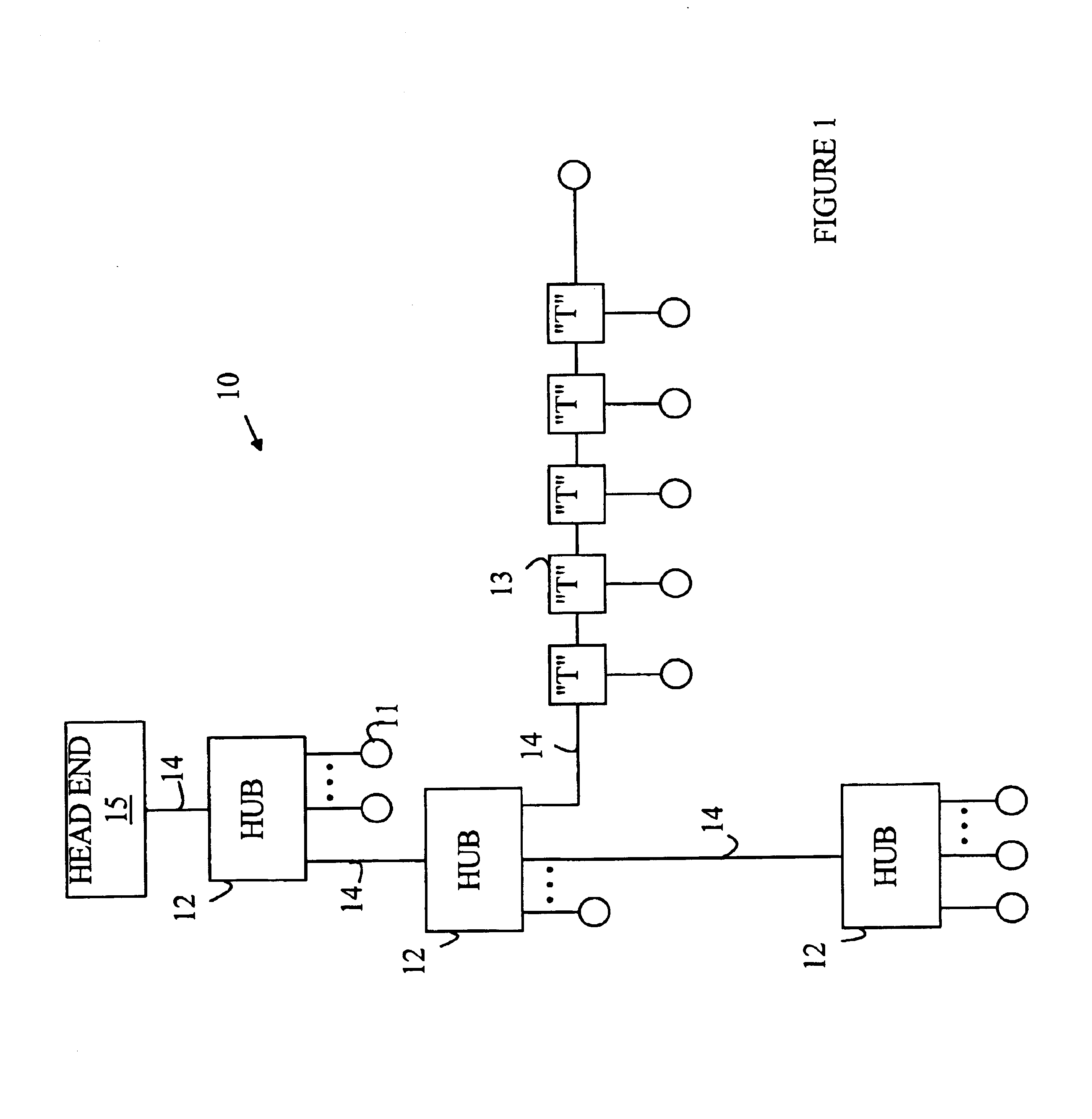
[0026]Refer now to FIG. 1 which is a block diagram of a network 10 according to the present invention for connecting a number of devices 11 to each other and to a head end 15 which is typically a server. Network 10 is constructed from a cable system 14 and two types of fan-out devices. Cable system 14 is based on twisted pairs for signal transmission; hence, the individual devices 11 must be connected via some form of fan-out device. The first type of fan-out device will be referred to as a hub. Hubs are shown at 12 in FIG. 1. A hub amplifies the signals, resynchronizes, and retransmits the amplified signals. As noted above, there is a limit to the number of hubs that can be connected in series, since the re-transmission function of each hub introduces “jitter” into the signals output therefrom.

[0027]To overcome the limit on the number of hubs that can be connected in series, the present invention utilizes a second type of fan-out device, referred to as a “T”. Exemplary Ts are shown...


PUM


Abstract

A network for connecting a plurality of devices and the components used in constructing the network. The network includes at least one fan-out device for connecting the devices to each other. The fan-out device includes a controller, a top port and a plurality of downstream ports. The controller monitors messages received by the ports and generates messages that are sent via the ports. The network also includes a plurality of network cables, one per port. The network preferably utilizes a cabling system that includes twisted pairs for communicating the messages via the Ethernet protocol and power conductors for distributing power to the various network devices. The fan-out device includes one power component associated with each of the ports. Each power component provides connections between the power lines in the network capble and the ports of the fan-out device. The power components are used to power the devices on the network and to monitor the power lines for problems. Switching circuitry in the power components allows the fan-out device to isolate cable runs connected thereto that have shorts or other problems. The fan-out device preferably stores a device identification number that the controller transmits on all of the ports in response to a message received on one of the downstream ports. The controller also generates a signal on the top port that causes any device connected to the fan-out device via the top port to ignore the message. One embodiment of the fan-out device provides a hub that is transparent to Ethernet protocols while not introducing the jitter into the signals associated with the re-transmission and synchronization functions performed by conventional hubs.

Description

FIELD OF THE INVENTION[0001]The present invention relates to network systems for connecting a plurality of data processing systems, and more particularly, to a network system that is adapted to industrial environments.BACKGROUND OF THE INVENTION[0002]In many control and monitoring applications one or more field busses are used to establish communication between the various sensors, actuators, controllers and other components typically found at the field level in such systems. Most of these field busses are either proprietary or of limited use outside of rather narrow application areas. There has been considerable interest in using a standard communication protocol such as Ethernet™ in these applications.[0003]Field level communications are typically established among sensors, actuators, controllers, and other devices (nodes) found in factory, industrial, environmental monitoring, agricultural and similar application environments. Unfortunately, applications in industrial settings ty...

Claims


Application Information

Patent Timeline
IPC IPC(8): H04L12/10H04L12/56
CPCH04L12/10H04L49/351
Inventor EIDSON, JOHN C.SITTE, HANS
Owner AGILENT TECH INC
Why Eureka
Try Eureka