
Illumination apparatus

Inactive Publication Date: 2005-05-10
TOYODA GOSEI CO LTD
View PDF9 Cites 53 Cited by
  • Summary
  • Abstract
  • Description
  • Claims
  • Application Information

AI Technical Summary

Benefits of technology

[0010]In the illumination apparatus configured thus, a part of light radiated from the LED light source and introduced into the light guide plate is reflected irregularly in outer circumferential portions (edge portions) of the character portions constituted by concave portions or convex portions. Thus, high-luminance light is observed in the outer circumferential portions of the character portions, so that the character portions, that is, the desired shapes are displayed (recognized). Since the desired shapes can be displayed by providing the concave portions or the convex portions in the light guide plate itself as described above, it is not necessary to provide a character plate separately. It is therefore possible to prevent unevenness in light emission, irregular reflection, reduction in light emission quantity, or the like, which might be caused by dust, water, or the like, if a character plate provided with light transmission holes were used as described above. In addition, it is possible to reduce the cost required for manufacturing such a character plate.
[0011]On the other hand, the LED light source is received in the groove portion provided in the light guide plate, and the groove portion is covered with a base member having its circumferential edge portion bonded to the light guide plate. The LED light source can be therefore prevented from being affected by dust or water. Thus, an illumination apparatus high in waterproof effect and superior in durability is arranged. In addition, since the LED light source is incorporated in the light guide plate, light emitted from the LED light source can be introduced into the light guide plate efficiently. Thus, an illumination apparatus high in luminous efficiency is provided.

Problems solved by technology

Thus, there is a fear that the surface of the light guide plate is damaged or polluted to cause unevenness in light emission, irregular reflection, reduction in light emission quantity, or the like.
Therefore, there is a fear that dust, water, or the like, enters a gap between the light source and the display plate.
Further, the manufacturing cost of the character plate subjected to etching or the like is high so that there is a room for improvement in cost.

Method used


Image

  • Illumination apparatus
  • Illumination apparatus
  • Illumination apparatus

Examples


Embodiment Construction

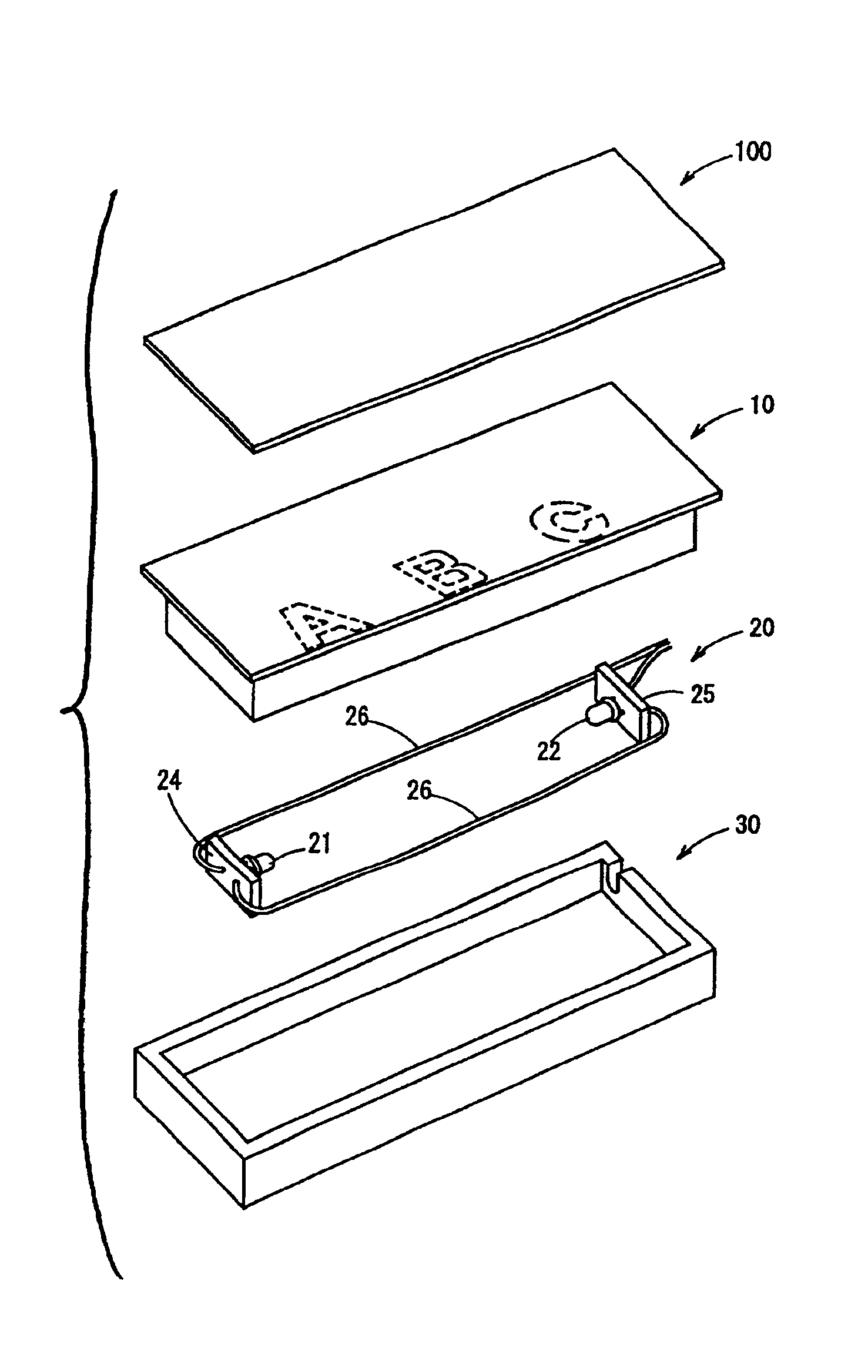
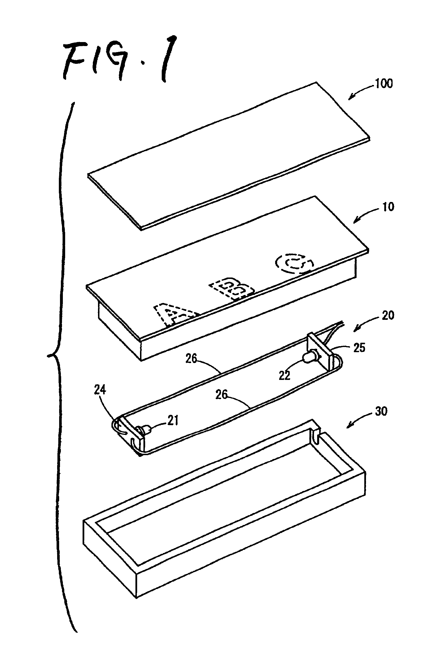
[0021]Respective constituents of the present invention will be described along with a scuff plate illumination apparatus 1 according to an embodiment of the present invention, by way of example. In use, the scuff plate illumination apparatus 1 is additionally provided on a side step portion of a car. Thus, the scuff plate illumination apparatus 1 displays desired shapes by means of light from an LED light source.

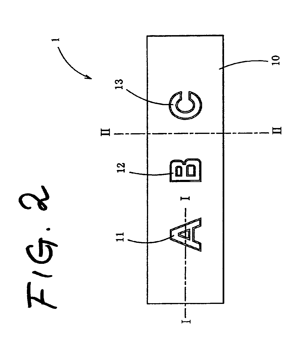
[0022]FIG. 1 is a perspective view showing the scuff plate illumination apparatus 1 which has not yet been assembled. FIG. 2 is a plan view showing the scuff plate illumination apparatus 1 which has been assembled, viewed from the light emission observable surface side thereof. In addition, FIGS. 3 and 4 are sectional views taken on line I—I and line II—II in FIG. 2 respectively. The configuration of the scuff plate illumination apparatus 1 will be described below with reference to the drawings.

[0023]As shown in FIG. 1, the scuff plate illumination apparatus 1 is schematical...


PUM


Abstract

An LED light source is received in a groove portion provided in a light guide plate. The groove portion is covered with a base member, and the circumferential edge of the base member is bonded to the light guide plate. Concave portions or convex portions having desired shapes are provided in a surface opposite to a light emission observable surface of the light guide plate so as to form character portions.

Description

CROSS REFERENCE TO THE RELATED APPLICATION[0001]The present application is based on Japanese Patent Application No. 2000-296635, which is incorporated herein by reference.BACKGROUND OF THE INVENTION[0002]1. Field of the Invention[0003]The present invention relates to an illumination apparatus, and particularly relates to an illumination apparatus for displaying a specific shape with light emitted from an LED light source.[0004]2. Description of the Related Art[0005]An illumination apparatus in which characters, graphic symbols, etc. are displayed on a scuff plate or the like is known as a vehicle-interior illumination apparatus. For example, there is a scuff plate illumination apparatus configured by the combination of a display plate and a light source. The display plate is designed so that a character plate formed of a metal plate provided with light transmission holes having desired shapes (for example, an aluminum plate etched to be provided with through holes partially) is disp...

Claims


Application Information

Patent Timeline
IPC IPC(8): F21V8/00G02B6/00G02B6/42G09F13/18H01L33/00
CPCB60Q1/323G02B6/0036G02B6/0021G02B6/009B60Q1/325
Inventor SHIBATA, MINORUYAMANAKA, OSAMUMUTO, MASANOBU
Owner TOYODA GOSEI CO LTD
Learn More