Filler device sub-assembly

a technology of a sub-assembly and a cap member, which is applied in the direction of packaging under special atmospheric conditions, packaging, packaging types, etc., can solve the problems of preventing air and/or other undesirable substances from entering the associated container before filling, unloading, capping, etc., and achieving the effect of facilitating longitudinal movement and rotational movemen

Inactive Publication Date: 2005-05-10
SCHOLLE CORP
View PDF36 Cites 14 Cited by
  • Summary
  • Abstract
  • Description
  • Claims
  • Application Information

AI Technical Summary

Benefits of technology

[0014]In another such embodiment, the at least one slot interfacing with the at least one follower of the inner cam assembly includes a longitudinal section and a rotational section. The positioning of the at least one follower of the inner cam in the longitudinal section facilitat

Problems solved by technology

While the above-identified fill assemblies have become commercially available for use in association with filler devices, problems associated with precluding air and/or other undesirable matter from entering an associated container before filling as well as uncapping, capping, and/or recapping at an operatively acceptabl

Method used


Image

  • Filler device sub-assembly
  • Filler device sub-assembly
  • Filler device sub-assembly

Examples


second embodiment

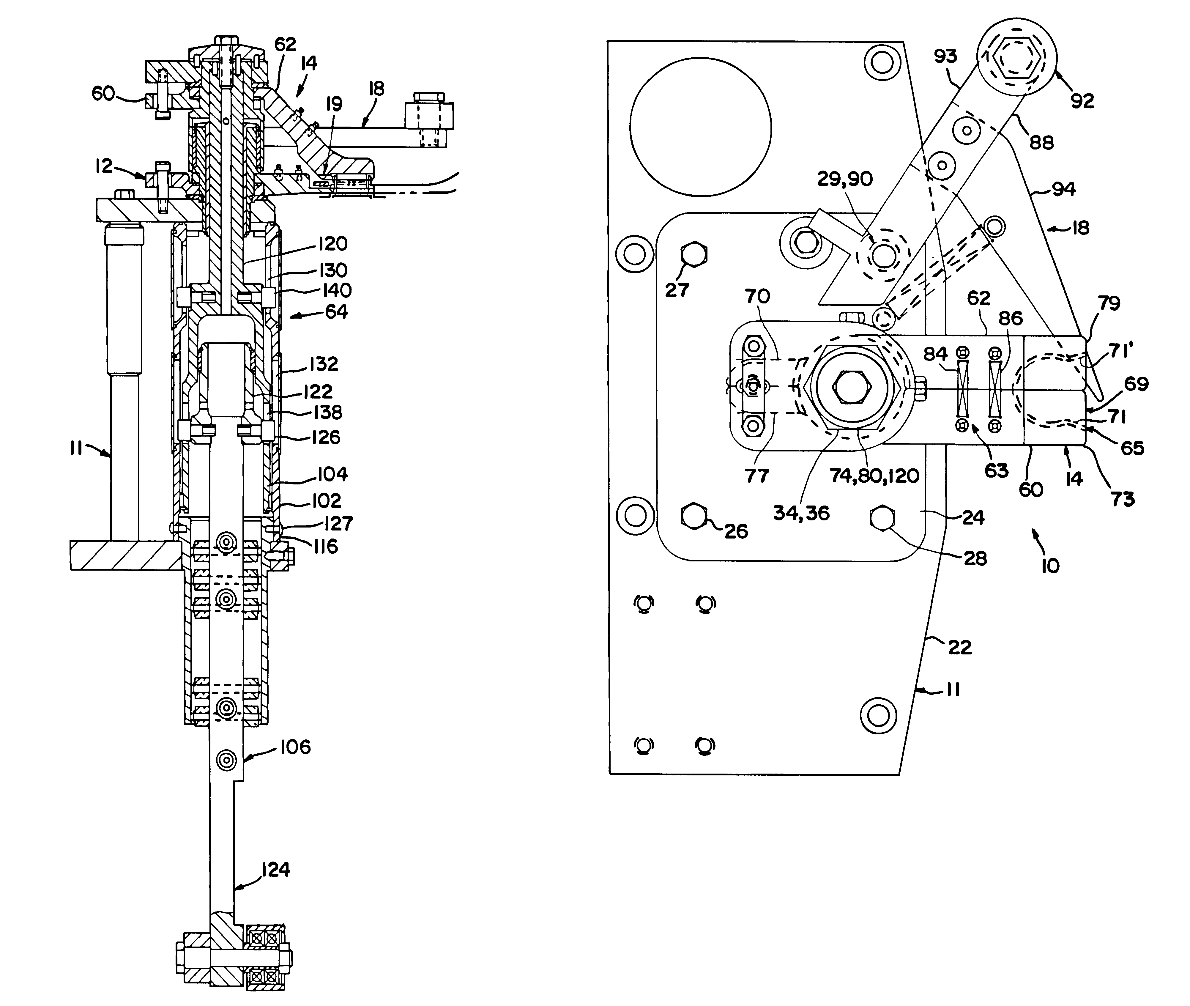
[0073]In a second embodiment, shown in FIG. 8, controllable cap gripper manipulating means 64 comprises inner cam 152, outer cam 156 and means 164 for controlling rotation of upper shaft member 120 relative to lifter shaft 106. Outer cam 156 is fixedly associated with base 22 of housing 11. Outer cam 156 includes cam surface 158 which comprises a substantially vertical cam surface upon which follower 154 is permitted to travel.

[0074]Inner cam 152 includes cam surface 160 and upper end 162. Cam surface 160 substantially corresponds to and cooperates with cam surface 158 of outer cam 156. The specific shape of cam surface 160 comprises a vertical section combined with an upwardly angled extension. Inner cam 152 is coaxially positioned within outer cam 156 such that inner cam 152 is capable of rotating within the confines of outer cam 156. As will be explained, follower 154 travels along cam surface 160 of inner cam 152 simultaneously with travel along surface 158 of outer cam 156.

[007...

first embodiment

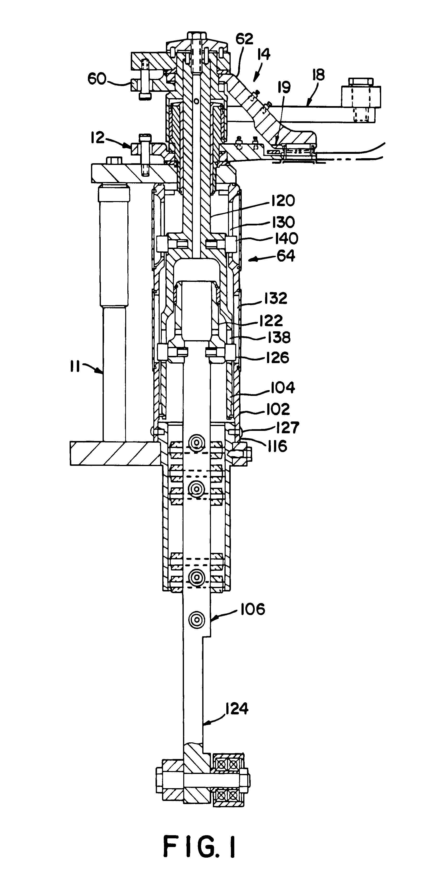
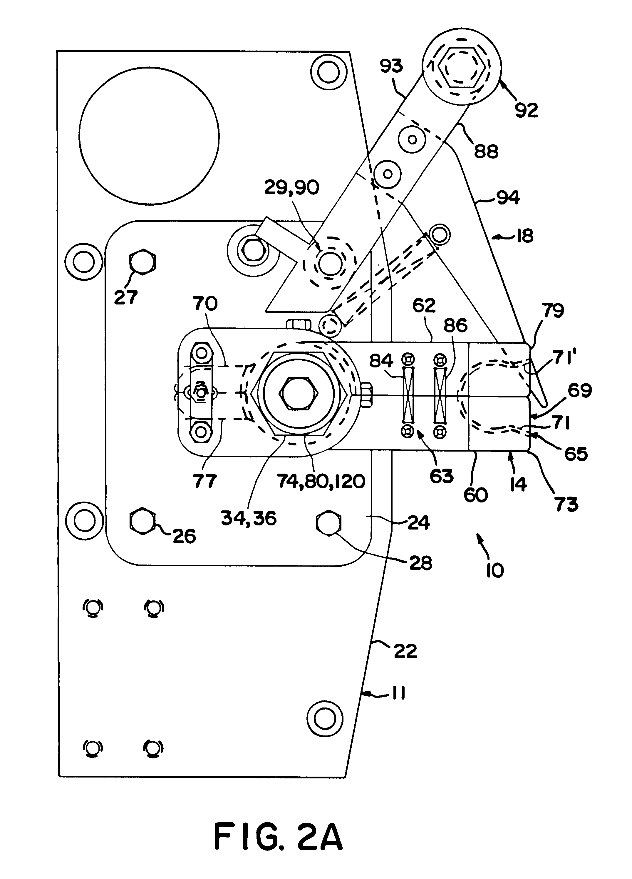
[0077]In operation of such an embodiment, after the cap and rim are retained and the substantial seal is created between the rim and the lower surface of the container (as described with respect to the first embodiment), the cap manipulating means is activated and directs the lifter shaft in an upward direction. The upward movement first directs the gripper arms away from the rim, thereby removing the cap from the rim.

[0078]The continued upward movement directs follower 154 against cam surface 160 of inner cam 152 and cam surface 158 of outer cam 156. During this time, spring 182 of locking assembly 170 maintains pin 172 in an upward orientation. In turn, locking spheres 175, 176 are in a first position wherein the lifter shaft and the upper shaft member are locked together and the movement of the lifter shaft coincides with the movement of the upper shaft member. In addition, the movement of the upper shaft member directs roller 168 to proceed vertically along slot 166 of upper sha...


PUM


Abstract

A filler device sub-assembly having a manipulator for manipulating a cap of a container comprising a first and second cap gripper arm and a member for controllably manipulating the cap gripper arms. The controllable manipulating member comprising an inner cam assembly, an outer cam assembly and a follower. The outer cam assembly extends at least partially about the inner cam assembly. One of the inner and outer cam assemblies coupled to the first and second cap gripper arms. The follower is associated with the inner cam assembly and the outer cam assembly. Movement of the lifter shaft imparts movement of the follower and relative movement of the inner cam assembly and the outer cam assembly, to in turn, longitudinally and rotatably move the cap gripper arms from a first position proximate to a container to a second position distally spaced from a container.

Description

CROSS-REFERENCE TO RELATED APPLICATION(S)[0001]This application claims the benefit of U.S. Provisional Application Ser. No. 60 / 122,977 filed Mar. 5, 1999, and U.S. Provisional Application Ser. No. 60 / 122,539 filed Mar. 3, 1999, both of which are hereby incorporated herein by reference in their entirety. In addition, this application relates to U.S. patent application Ser. No. 09 / 871,562 filed May 31, 2001, U.S. Provisional Application Ser. No. 60 / 208,185 filed May 31, 2000 and PCT Patent Application Serial No. PCT / US01 / 17536 filed May 31, 2001, all of which are hereby incorporated herein by reference in their entirety.BACKGROUND OF THE INVENTION[0002]1. Field of the Invention[0003]The present invention relates in general to a filler device sub-assembly, and more particularly, to a filler device sub-assembly, which among other things, substantially precludes air and / or other matter from undesirably entering an associated container upon and / or prior to filling of the same, which facil...

Claims


Application Information

Patent Timeline
IPC IPC(8): B65B3/04B65B7/28
CPCB65B7/28B65B3/04
Inventor EDWARDS, SIMON P.RESTERHOUSE, MICHAEL R.JOHNSON, RANDALL L.SZABO, II, ROBERT B.
Owner SCHOLLE CORP
Why Eureka
Try Eureka