Magnetic attachment of a bed knife in a reel mower assembly

Inactive Publication Date: 2005-05-10
TEXTRON INNOVATIONS +1
View PDF13 Cites 19 Cited by
  • Summary
  • Abstract
  • Description
  • Claims
  • Application Information

AI Technical Summary

Benefits of technology

[0014]The magnetic attachment also reduces maintenance costs by allowing the bed knife to be pulled away from its magnetic attachment and r

Problems solved by technology

Such reel mowers are more expensive and require more maintenance than rotary mowers, however they are preferred by golf courses and the like where appearance and healthy grass are important.
A reel -mower unit such as is used by a golf course or the like may comprise eight or ten individual reel mower assembly, and changing bed knives on such a mower unit requires significant labor time and corresponding downtime.
As well, the screws fix the bed knife to the bed bar su

Method used


Image

  • Magnetic attachment of a bed knife in a reel mower assembly
  • Magnetic attachment of a bed knife in a reel mower assembly
  • Magnetic attachment of a bed knife in a reel mower assembly

Examples


Example

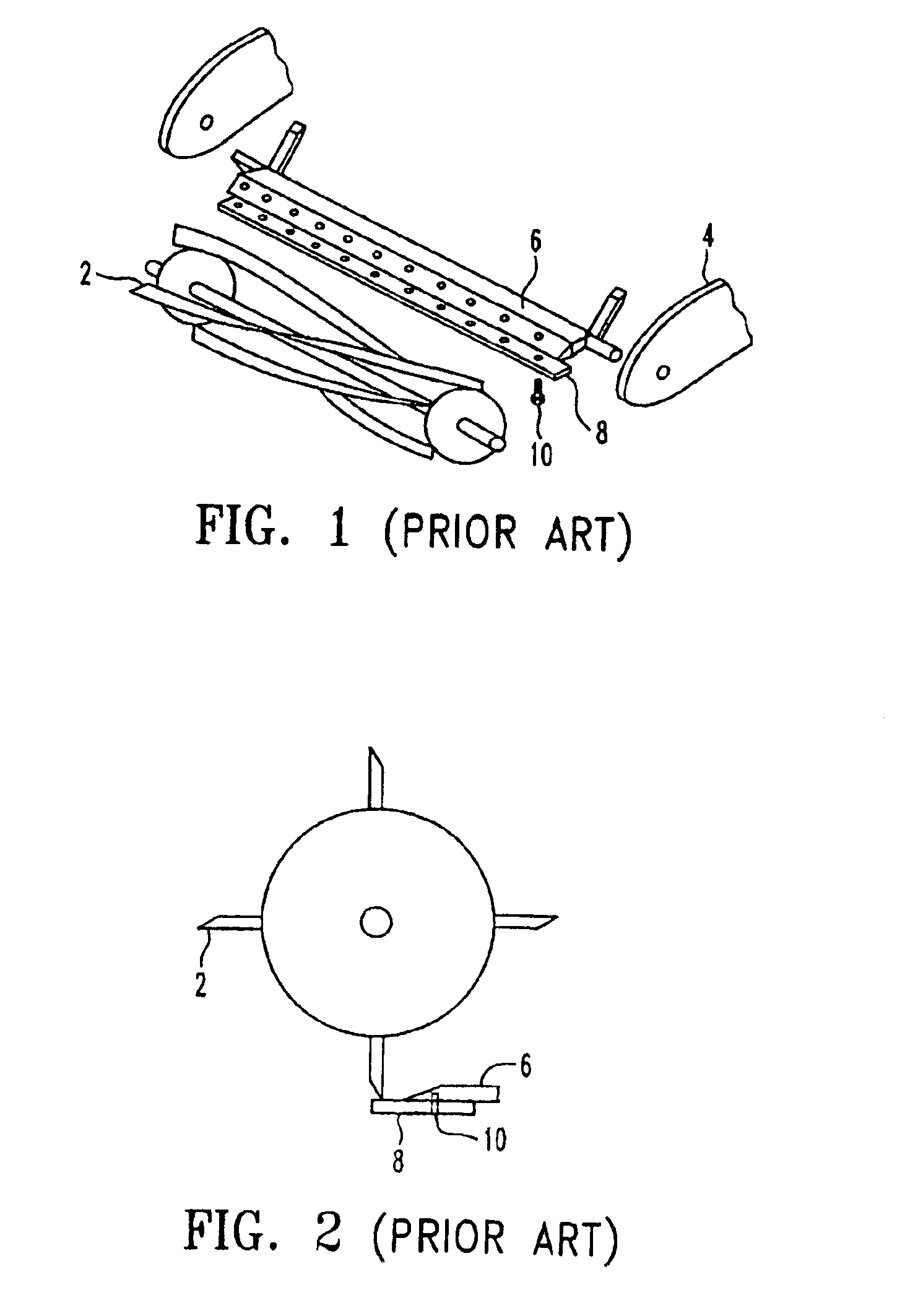
[0026]FIG. 1 schematically illustrates the major parts of a prior art reel mower assembly comprising a mower reel 2 rotatably mounted to a frame 4. A drive, not shown, is operative to rotate the reel 2 about a reel axis RA. A bed bar 6 forms a portion of the frame 4, and the bed knife 8 is attached to the bed bar 6 by screws 10. Typically some adjustment mechanism, not shown, is provided to vary the position of the bed bar 6 with respect to the reel 2 so that the proper cutting relationship between the bed knife 8 and reel 2 may be achieved. FIG. 2 illustrates schematically the orientation of the reel 2, the bed bar 6, and the bed knife 8 of the prior art.

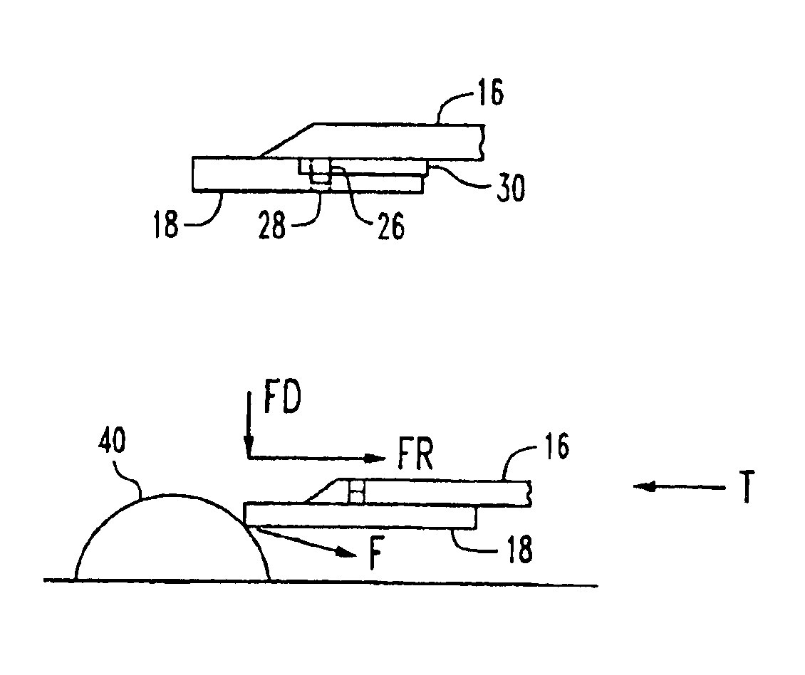
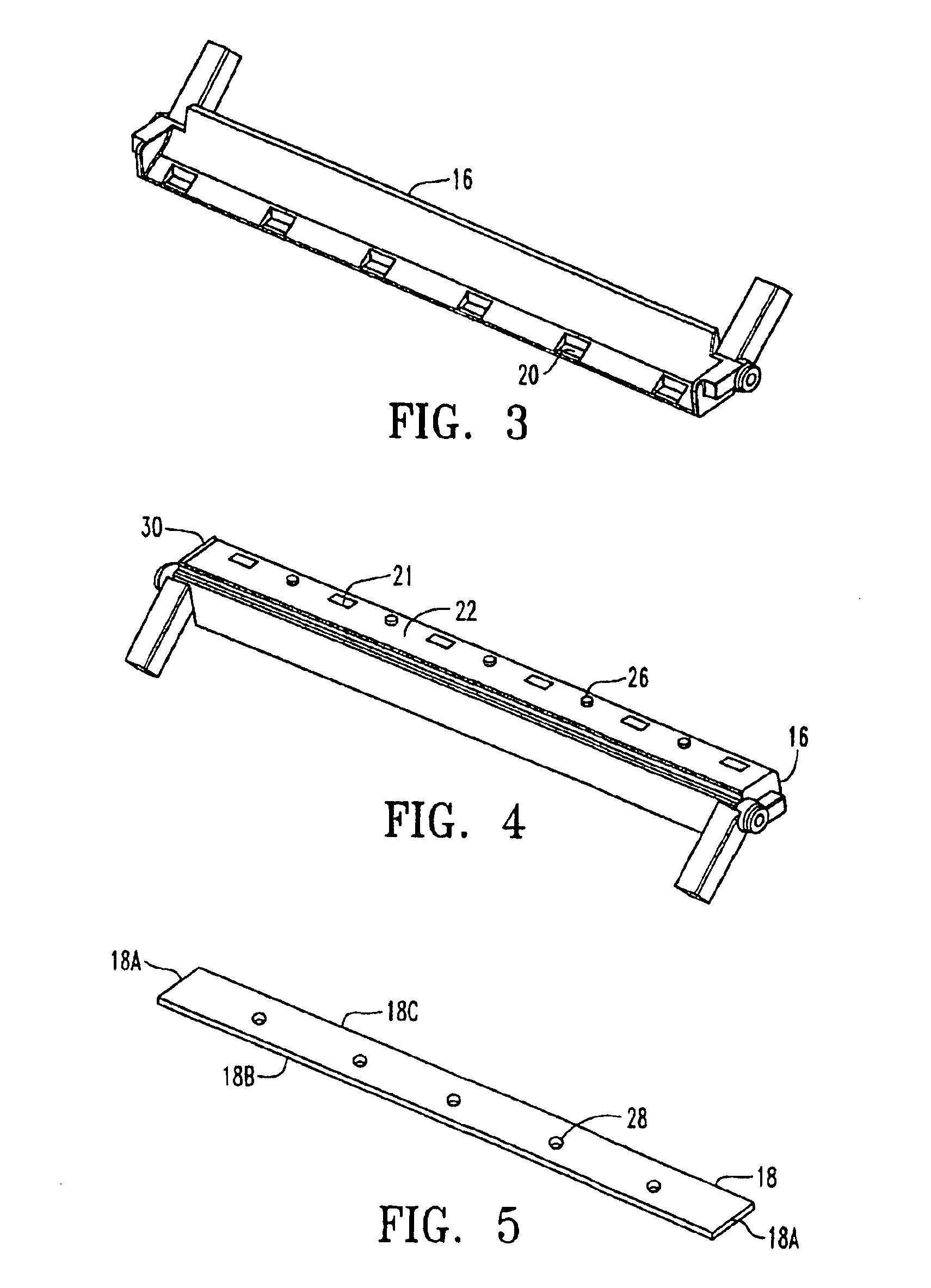
[0027]FIGS. 3 and 4 illustrate an embodiment of a magnetic bed bar 16 of the invention. The illustrated bed bar 16 is configured to attach to the frame 4 of the prior art reel mower assembly of FIG. 1 in the same manner as the prior art bed bar 6, so that the magnetic bed bar 16 can be retro-fit to existing reel mower assemblies. T...


PUM


Abstract

A reel mower assembly comprises a mower reel rotatably mounted to a frame, and a drive operative to rotate the reel about a reel axis. A plurality of magnets are mounted on the frame and a bed knife is magnetically held against the magnets in an operating position such that the bed knife is oriented in cutting relationship with the reel. When the bed knife is in an operating position, sliding movement of the bed knife with respect to the magnets while allowing the bed knife to move away from the magnets may be prevented, when a separating force is exerted on the bed knife in a direction away from the magnets that is greater than an attractive force exerted on the bed knife by the magnets.

Description

[0001]This invention generally relates to improved reel mower assemblies and reel mower units incorporating such assemblies. More specifically, it relates to an alternative attachment of the bed knife to the mower reel assembly which reduces maintenance costs.BACKGROUND[0002]Reel mowers use a scissoring action to shear grass and like foliage, rather than caring the leaves. Such reel mowers are more expensive and require more maintenance than rotary mowers, however they are preferred by golf courses and the like where appearance and healthy grass are important. Individual reel mower assemblies are quite narrow, and consequently reel mower units commonly comprise a plurality of side-by-side reel mower assemblies.[0003]Examples of such mowers are disclosed in U.S. Pat. Nos. 5,291,724, 5,477,666 and 6,318,059. In a typical reel mower assembly, an attachment member, commonly called a bed bar; is attached to the apparatus in rigid relationship to the reel, and a replaceable bed knife is a...

Claims


Application Information

Patent Timeline
IPC IPC(8): A01D34/412A01D34/62
CPCA01D34/62Y10S56/20A01D2101/00
Inventor BUCHKO, JEFF
Owner TEXTRON INNOVATIONS
Why Eureka
Try Eureka