Method of dispensing particles, a particle filling line, and apparatus for dispensing particles

a technology of particle filling and particle filling, which is applied in the direction of liquid transferring device, liquid handling, packaging goods type, etc., can solve the problems of poor weight control, limited filling rate, and overfilling of cartridges

Inactive Publication Date: 2005-05-10
XEROX CORP
View PDF12 Cites 26 Cited by
  • Summary
  • Abstract
  • Description
  • Claims
  • Application Information

AI Technical Summary

Problems solved by technology

For many larger toner cartridges the filling rates are limited by the stability of toner replenishment to the filler hopper.
When toner is passed through the toner filling line too fast the toner becomes fluid and causes problems such as over-filled cartridges, poor weight control, and free flow.

Method used


Image

  • Method of dispensing particles, a particle filling line, and apparatus for dispensing particles
  • Method of dispensing particles, a particle filling line, and apparatus for dispensing particles
  • Method of dispensing particles, a particle filling line, and apparatus for dispensing particles

Examples


Embodiment Construction

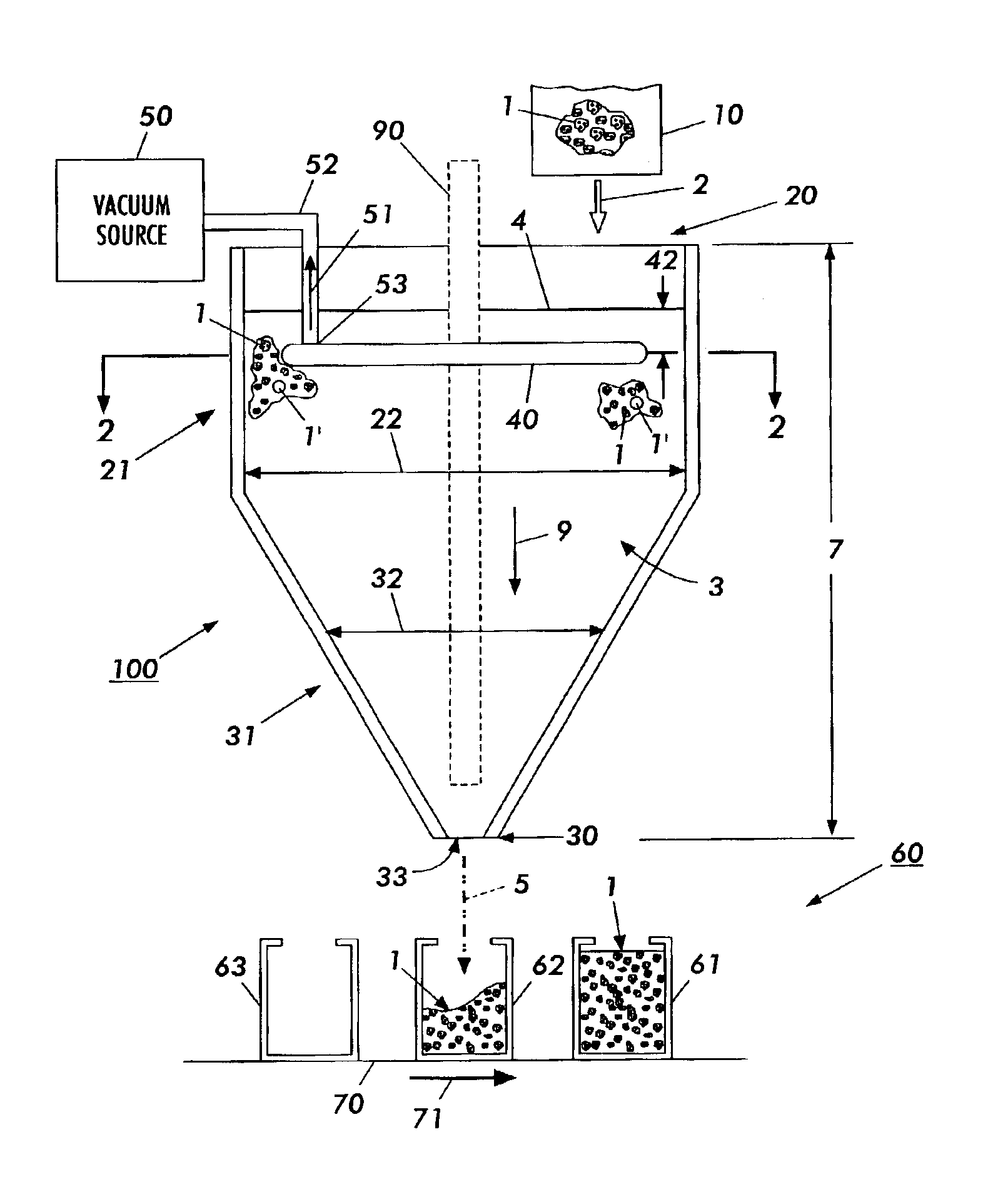
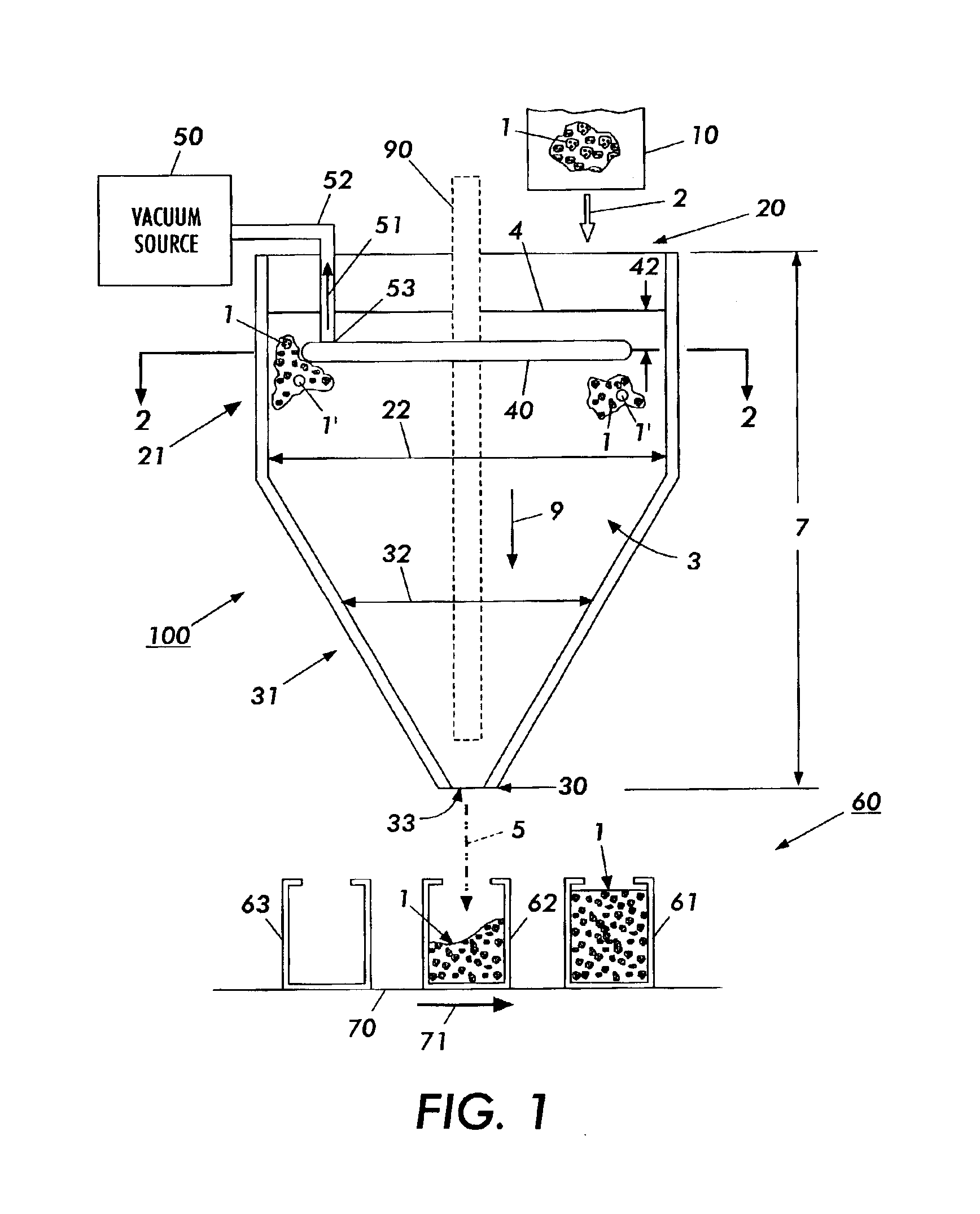
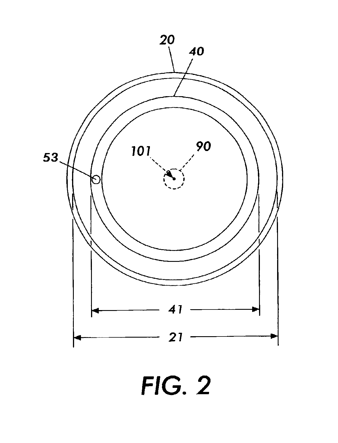
[0013]Briefly, a particle filling line comprises a vertical conduit that is arranged to dispense particles to one or more containers that are disposed on an included movable conveyor belt. The conduit includes a conduit hollow, a conduit top and a conduit bottom that defines an outlet. Particles supplied to the conduit top flow through the outlet to fill the containers. The conduit is filled with particles. The particles include a particle spacing air. The particle spacing air is reduced by means of a porous tube that is fixed in the conduit hollow and coupled to a vacuum source. After reducing the particle spacing air, the particles flow through the outlet to be received in the containers. In one embodiment, the porous tube is substantially horizontally-oriented. In one embodiment, the porous tube forms a toroid-shaped ring.

[0014]Referring to FIG. 1, there is shown a particle filling line comprising a vertically-oriented conduit 100. The conduit 100 includes a conduit hollow 3, a c...


PUM

PropertyMeasurementUnit
pressureaaaaaaaaaa
outer diameteraaaaaaaaaa
linear lengthaaaaaaaaaa

Abstract

A particle filling line comprises a vertical conduit that is arranged to dispense particles to one or more containers that are disposed on an included movable conveyor belt. The conduit includes a conduit hollow, a conduit top and a conduit bottom that defines an outlet. Particles supplied to the conduit top flow through the outlet to fill the containers. The conduit is filled with particles. The particles include a particle spacing air. The particle spacing air is reduced by means of a porous tube that is fixed in the conduit hollow and coupled to a vacuum source. After reducing the particle spacing air, the particles flow through the outlet to be received in the containers.

Description

INCORPORATION BY REFERENCE OF OTHER U.S. PATENTS[0001]The applicant hereby incorporates by reference the disclosures of the following U.S. patents verbatim and with the same effect as though all such disclosures were fully and completely set forth herein:[0002]U.S. Pat. No. 6,021,821 to Paul M. Wegman, entitled “Particulate processing apparatus”, granted 8 Feb. 2000, hereinafter referred to as the “Wegman '821 patent”;[0003]U.S. Pat. No. 6,056,025 to Paul M. Wegman, entitled “High speed air nozzle for particulate filling system”, granted 2 May 2000, hereinafter referred to as the “Wegman '025 patent”;[0004]U.S. Pat. No. 6,196,278 to Paul M. Wegman et al., entitled “Powder filling utilizing vibrofluidization”, granted 6 Mar. 2001, hereinafter referred to as the “Wegman '278 patent”;[0005]U.S. Pat. No. 6,484,764 to Paul M. Wegman et al., entitled “Filling apparatus having an even-filling nozzle”, granted 26 Nov. 2002, hereinafter referred to as the “Wegman '764 patent”; and[0006]U.S. ...

Claims


Application Information

Patent Timeline
Patent Type & Authority Patents(United States)
IPC IPC(8): B65B1/00B65B1/26B67D99/00B65B39/04
CPCB65B39/04B65B1/26
Inventor HUSS, TIMOTHY L.
Owner XEROX CORP
Why Eureka
Try Eureka