Rotary tool

a technology of rotary tools and rotary plates, which is applied in the direction of wrenches, power driven tools, manufacturing tools, etc., can solve the problems of limiting the operating speed of impact wrenches, difficult to loosen or remove fasteners, and over-tightening fasteners, etc., and achieves the effect of difficult to loosen or remov

Inactive Publication Date: 2005-05-10
INGERSOLL RAND IND U S INC
View PDF53 Cites 38 Cited by
  • Summary
  • Abstract
  • Description
  • Claims
  • Application Information

AI Technical Summary

Benefits of technology

[0003]When an operator tightens a fastener (e.g., a bolt, a screw, a nut, and the like) using a conventional impact wrench, the impact wrench may over-torque or over-tighten the fastener causing the fastener to break. Over-tightened fasteners may be difficult to loosen or remove from a workpiece.

Problems solved by technology

When an operator tightens a fastener (e.g., a bolt, a screw, a nut, and the like) using a conventional impact wrench, the impact wrench may over-torque or over-tighten the fastener causing the fastener to break.
Over-tightened fasteners may be difficult to loosen or remove from a workpiece.
Conventional impact wrenches often include torque limiting mechanisms that limit the operating speed of the impact wrench.

Method used


Image

  • Rotary tool
  • Rotary tool
  • Rotary tool

Examples


Embodiment Construction

[0022]As used herein and in the appended claims, the terms “upper”, “lower”, “first”, and “second” are for the purposes of description only and are not intended to imply any particular orientation, order, or importance.

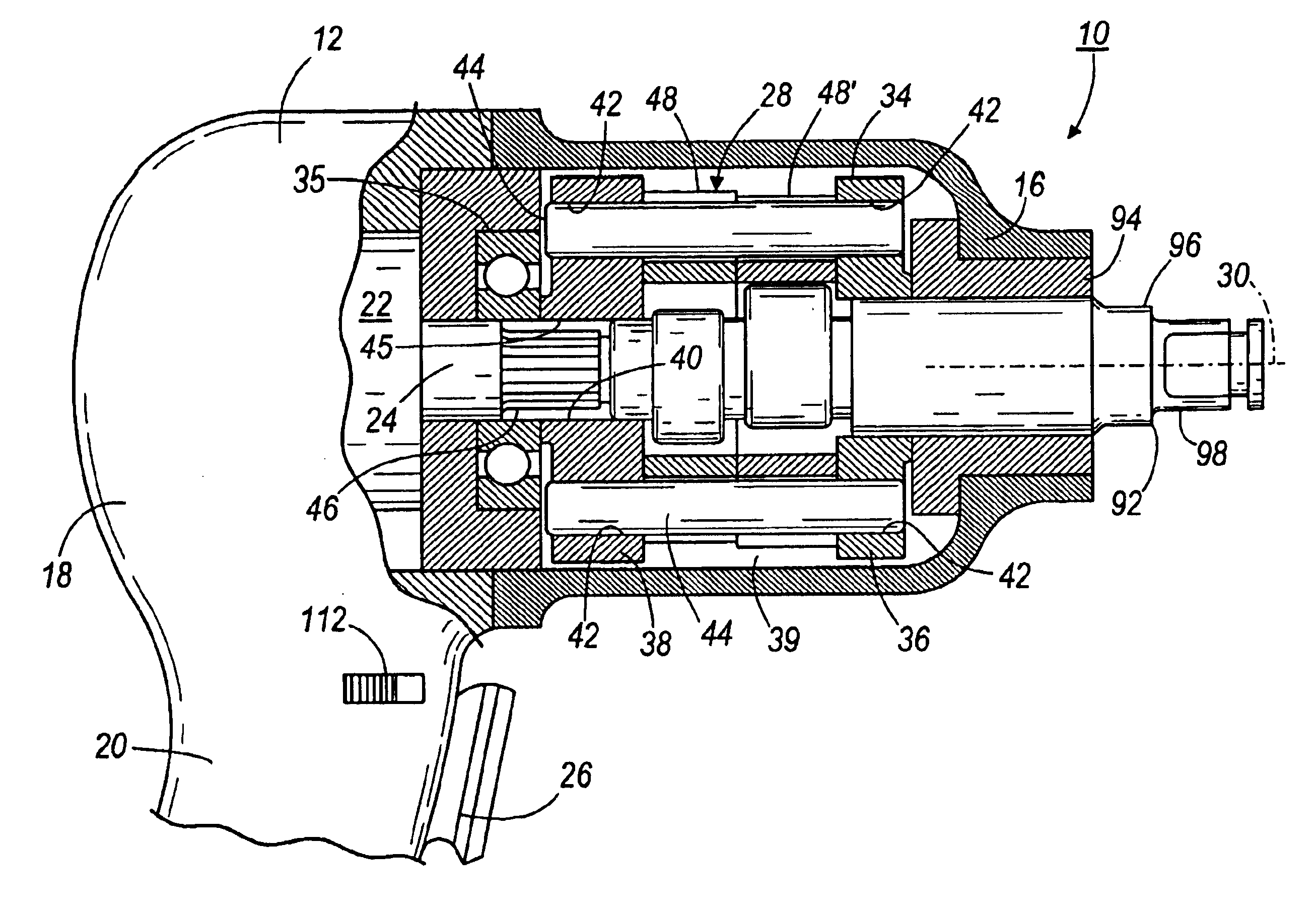
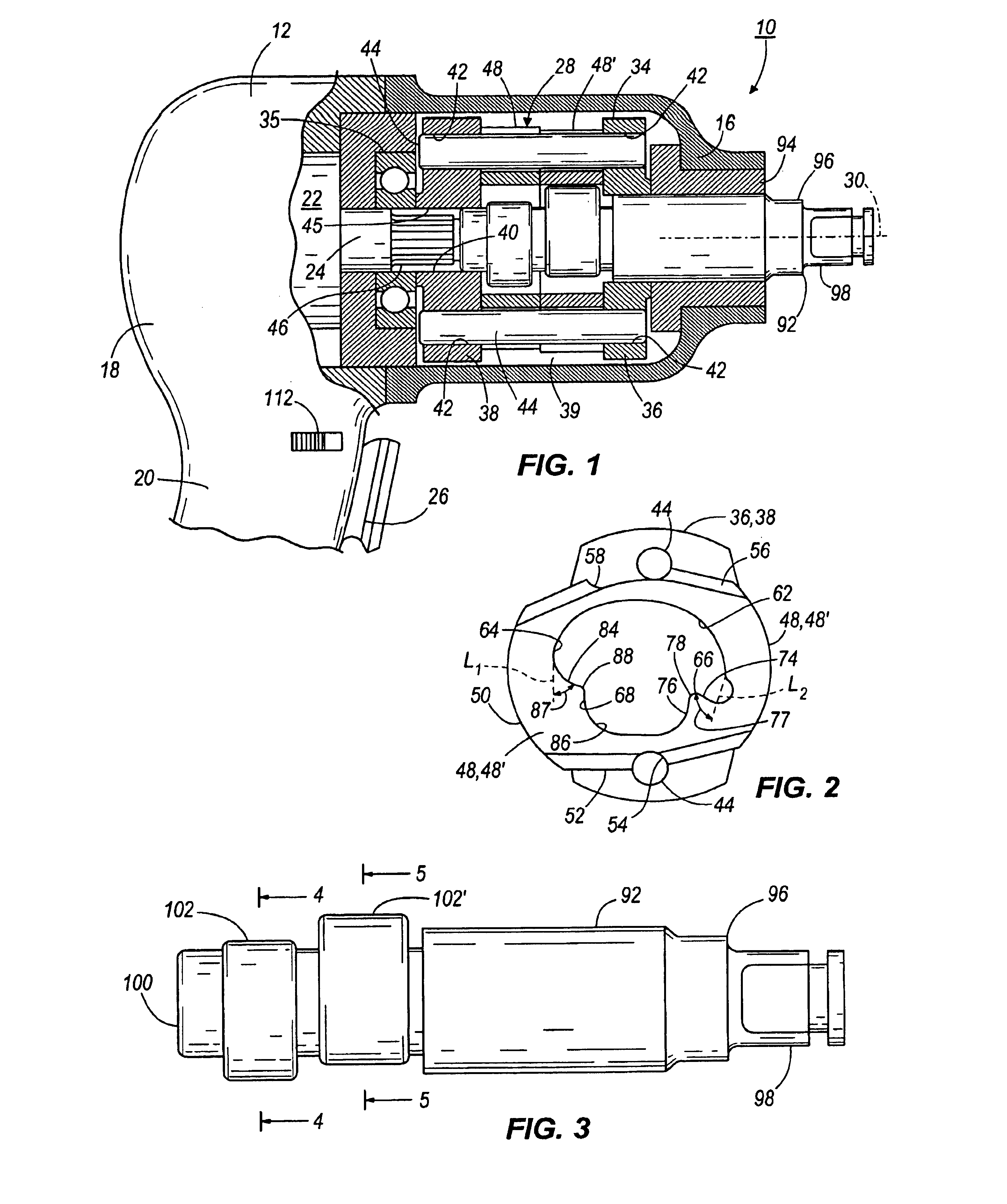
[0023]A rotary tool, such as, for example, an impact wrench 10 embodying aspects of the present invention, is illustrated in FIG. 1. The impact wrench 10 includes a housing 12 having a forward end 16 and a rearward end 18, an operator's grip or handle 20, a motor 22 (e.g., an air motor or an electric motor) having a motor shaft 24, a trigger 26 operably coupled to the motor 22 to control motor speed, and a rotary drive system 28. The motor shaft 24 defines an axis 30, which extends axially through the impact wrench 10.

[0024]The rotary drive system 28 includes a frame or carrier 34 positioned in the forward end 16 of the housing 12. Bearing 35 supports the frame 34 in the housing 12 and facilitates rotation of the frame 34 about the axis 30 with respect to the housing ...


PUM


Abstract

A rotary tool, such as an impact wrench, operable in a forward mode and a reverse mode. The rotary tool includes a housing having a forward end and supporting a motor. The motor has a motor shaft extending axially through the housing and defining an axis. The rotary tool also include a frame supported in the housing and being rotatable relative to the housing about the axis, an output shaft supported in the forward end of the housing and rotatable about the axis, and a hammer pivotably coupled to the frame and defining a central aperture. The hammer has a first jaw and a second jaw extending into the central aperture. The first jaw and the second jaw are non-symmetrical.

Description

FIELD OF THE INVENTION[0001]The present invention relates to rotary tools and, more particularly, to a drive system for a rotary tool.BACKGROUND OF THE INVENTION[0002]A rotary tool, such as an impact wrench, generally includes a housing supporting a motor, an output shaft having a first end adapted to engage a fastener and a second end having an anvil, and a drive mechanism operable to drive the output shaft. In impact wrenches, the drive mechanism generally includes one or more tilting hammers or dogs, which are rotated about a central axis by the motor and periodically impact the anvil to hammer or drive the output shaft in either a forward or a reverse direction. An operator generally toggles a switch located on the housing to change the rotation direction of the output shaft between the forward and reverse directions. Generally, the operator operates the tool in the forward direction to thread the fastener into engagement with a workpiece, and in a reverse direction to unthread ...

Claims


Application Information

Patent Timeline
Patent Type & Authority Patents(United States)
IPC IPC(8): B25B21/02B25B19/00B25D13/00B25D15/00
CPCB25B21/026B25B21/02
Inventor COLANGELO, III, LOUIS J.COOPER, TIMOTHY R.
Owner INGERSOLL RAND IND U S INC
Why Eureka
Try Eureka