Frame assembly for scooter-type vehicle

a frame assembly and scooter technology, applied in the direction of machines/engines, jet propulsion mounting, cycle equipment, etc., can solve the problems of increasing the overall cost of the scooter, difficult assembly of the components within the space defined between the upper and lower rails, and relatively heavy overall frame assembly, etc., to achieve the desired level of strength, simple and efficient assembly of components, and lower weight

Inactive Publication Date: 2005-05-10
YAMAHA MOTOR CO LTD
View PDF14 Cites 21 Cited by
  • Summary
  • Abstract
  • Description
  • Claims
  • Application Information

AI Technical Summary

Benefits of technology

[0009]Accordingly, a need exists for a scooter-type vehicle frame assembly that has a desired level of strength and is lower in weight than previous scooter frame assemblies. In addition, a need exists for a scooter-type vehicle frame assembly that permits simpler and more efficient assembly of components to the frame assembly. In one arrangement, upper and lower frame portions are provided, wherein the lower frame portion is detachably coupled to the upper frame portion. Such an arrangement permits components to be assembled to the lower frame portion and upper frame portion, separately, before the upper and lower portions are coupled to one another. Accordingly, efficient assembly is facilitated because of the ease in which components may be assembled to the separate upper and lower frame portions.

Problems solved by technology

As a result of the welded-up construction of the frame assembly, assembly of the components within the space defined between the upper and lower rails is difficult.
Accordingly, the overall cost of the scooter is increased due to the time required for assembly.
In order to achieve a desired level of strength, the frame assembly of a scooter typically is constructed from relatively thick steel tubing, which results in the overall frame assembly being relatively heavy.

Method used


Image

  • Frame assembly for scooter-type vehicle
  • Frame assembly for scooter-type vehicle
  • Frame assembly for scooter-type vehicle

Examples


Embodiment Construction

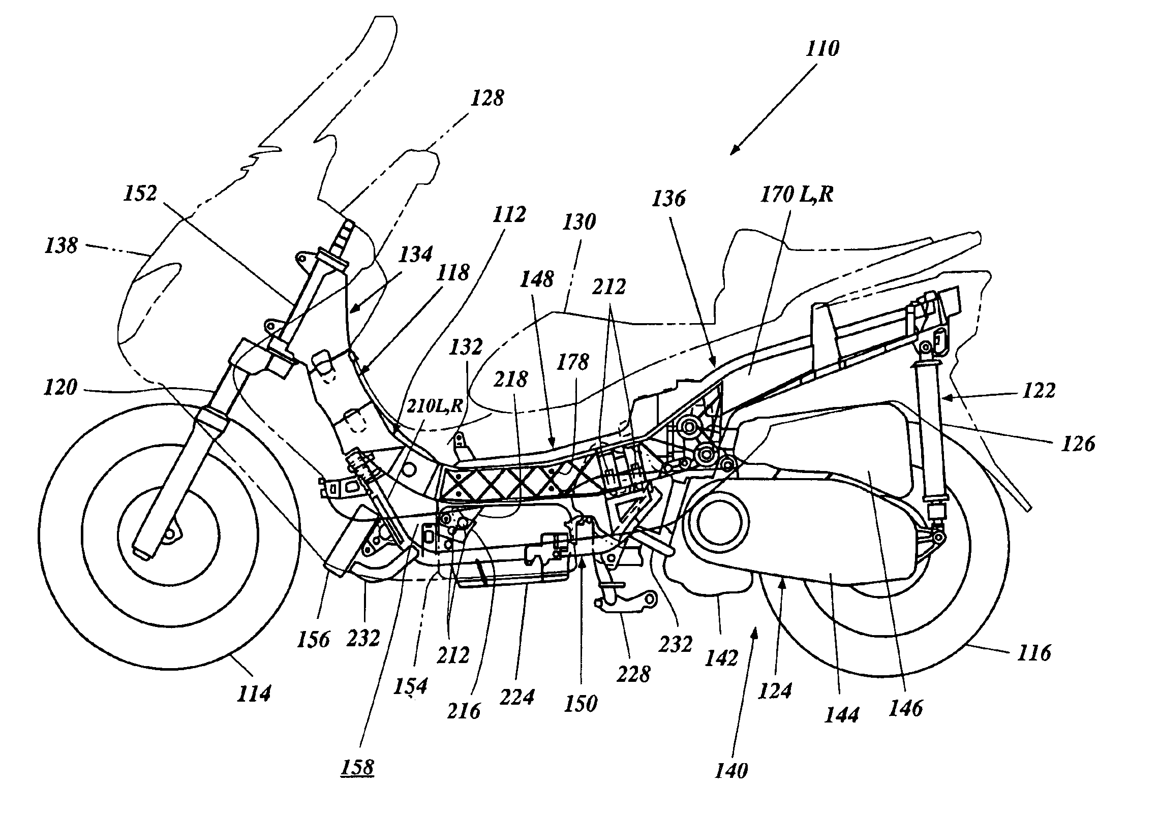
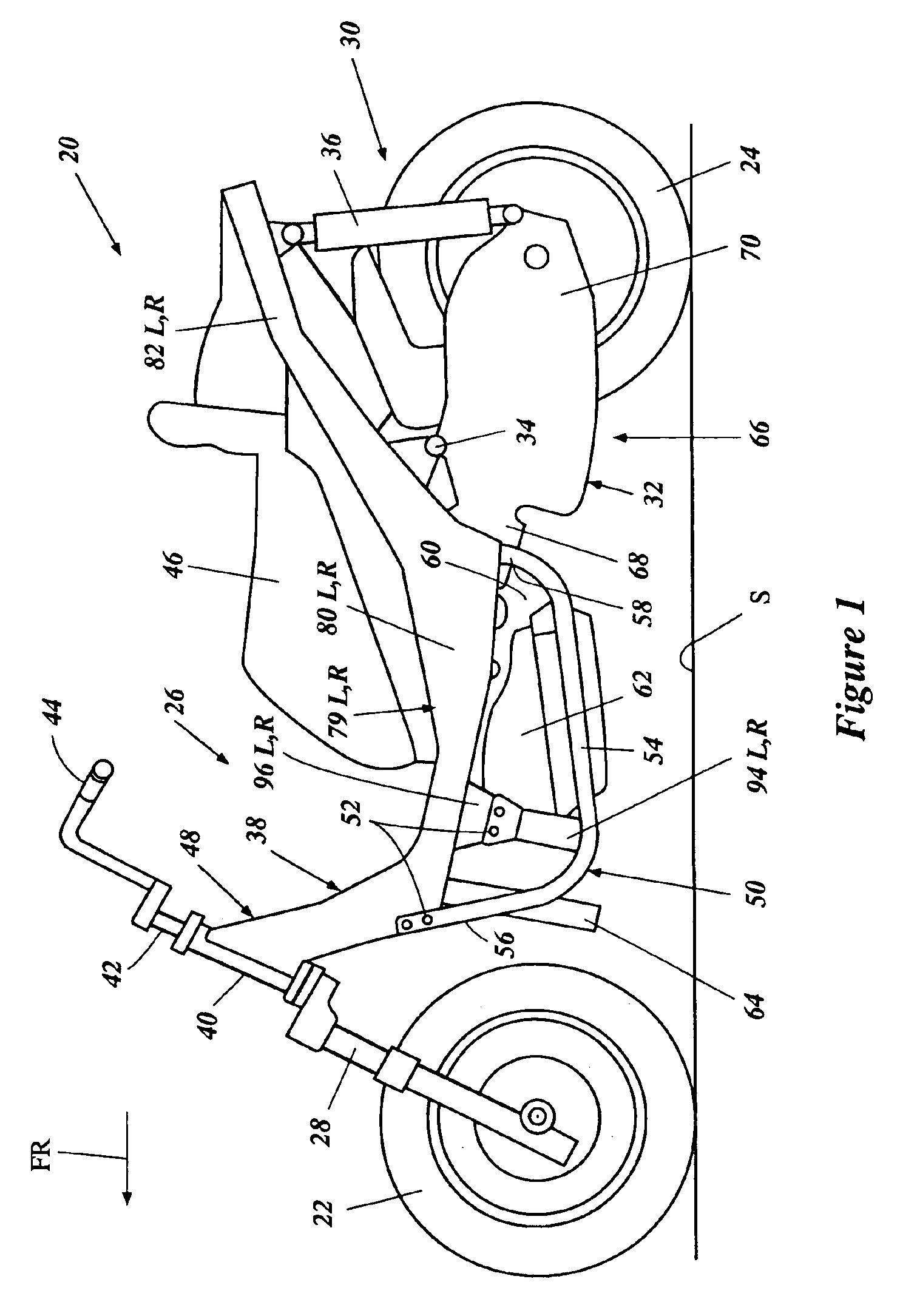
[0029]FIG. 1 illustrates a two-wheeled, straddle type scooter vehicle, or scooter, generally indicated by the reference numeral 20. Although the frame assembly of the present invention may be utilized on a wide variety of vehicles, the frame assembly is described in the context of a scooter 20 herein. Accordingly, a preferred embodiment of a scooter 20 will be described in general detail to assist the reader's understanding of a preferred embodiment of use of the present frame assembly.

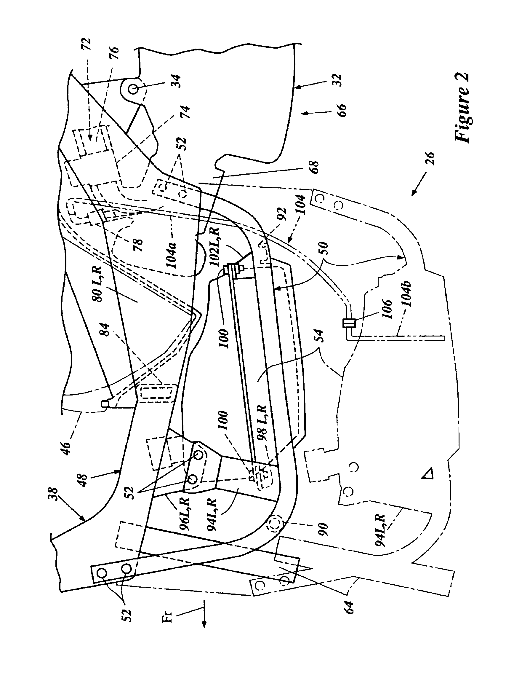
[0030]The scooter 20 will be described with reference to a coordinate system wherein a central, longitudinal plane CP (FIG. 3) passes vertically, lengthwise through the center of the scooter 20. A lateral plane is vertically-oriented and normal to the central plane CP. Relative heights are expressed as elevations from a surface S (FIG. 1) upon which the scooter 20 rests. In FIGS. 1 through 3, an arrow FR indicates a direction of forward travel of the scooter 20. The terms “right” and “left” indicate r...


PUM


Abstract

A frame assembly for a scooter-type vehicle having at least one front wheel, at least one rear wheel and a vehicle body. The frame assembly includes a head tube, which supports a front wheel suspension assembly of the vehicle. An upper frame extends from the head tube to a rearward end of the vehicle body. A swingarm is pivotally supported by the upper frame and supports a rear wheel of the vehicle. The frame assembly may include a lower frame removeably coupled to the upper frame and defining a space therebetween. The lower frame preferably supports at least one component of the scooter-type vehicle in the space, such as a fuel tank, for example. In one arrangement, the upper frame includes a forward portion and a rearward portion. The rearward portion includes at least one elongated, channel-shaped frame member having a forward section and a rearward section. Preferably, the forward section has an open side facing in a lateral direction and the rearward section has an open side facing in a vertical direction.

Description

RELATED APPLICATIONS[0001]This application is related to, and claims priority from, Japanese Patent Application Nos. 2001-381851, filed Dec. 14, 2001, 2002-042934, filed Feb. 20, 2002 and 2002-291982, filed Oct. 4, 2002, the entireties of which are expressly incorporated by reference herein.BACKGROUND OF THE INVENTION[0002]1. Field of the Invention[0003]The present invention relates generally to vehicle frame assemblies. More particularly, the present invention relates to a frame assembly for a scooter-type vehicle.[0004]2. Description of the Related Art[0005]Scooter-type vehicles, or scooters, include a frame assembly, which usually supports a body of the scooter, along with front and rear wheels of the scooter. Typically, front and rear suspension assemblies are operatively positioned between the front and rear wheels and the frame assembly. The front suspension assembly commonly is a telescopic fork arrangement, while the rear suspension assembly is a swingarm-type arrangement. I...

Claims


Application Information

Patent Timeline
Patent Type & Authority Patents(United States)
IPC IPC(8): B62K11/00B62K11/06B62K11/10F02B61/02F02B61/00B62K11/04B62K19/12B62K19/24B62K25/20
CPCB62K11/06F02B61/02B62K11/10B62K2202/00
Inventor HAKAMATA, TAKEOITAJIKI, SHUNICHI
Owner YAMAHA MOTOR CO LTD
Why Eureka
Try Eureka