Ophthalmic lens storage container

a technology for storing containers and lenses, applied in the direction of containers preventing decay, caps, liquid handling, etc., to achieve the effect of preventing undesired separation of cover sheets, stable opening of cavities, and preventing undesirable separation of covers

Inactive Publication Date: 2005-05-10
MENICON CO LTD
View PDF20 Cites 37 Cited by
  • Summary
  • Abstract
  • Description
  • Claims
  • Application Information

AI Technical Summary

Benefits of technology

[0024](11) An ophthalmic lens storage container according to any one of the above-indicated modes (1)-(10), wherein at least one circumferential portion of the sealing zone extends radially outward to thereby provide a seal-retaining portion that allows the cover sheet, which is partially stripped from the flange to expose the cavity substantially entirely, to be retained in the flange. According to this mode of the invention, after the sealed cavity is opened, the cover sheet is still sealed at the seal retained portion and held in sealed to the container body, making it possible to handle the opened container body and the cover sheet as an integral member. Preferably, the dimension of the seal-retaining portion is sufficiently made larger in a direction perpendicular to a direction in which the cover sheet is stripped from the flange than other directions, thereby effectively preventing undesirably separation of the cover sheet from the container body upon the opening of the storage container. In the ophthalmic lens storage container provided with the seal-retaining portion according to the present mode of the invention, the cover sheet is desirably formed of a specific material so that the cover sheet partially stripped off from the flange to expose the cavity is held in its deformed state where the cover sheet is still secured at the seal-retaining portion in a generally upright attitude to keep the cavity open.
[0025](12) An ophthalmic lens storage container according to the above-indicated mode (10), wherein the sealing zone extend radially outward to provide a seal-retaining portion at another circumferential portion that is opposed to the at least one circumferential portion where the beak-like portion is provided with the cavity interposed therebetween, the seal-retaining portion allows the cover sheet, which is partially stripped from the flange including the beak-like portion of the sealing zone to expose substantially entirely the cavity, to be retained in the flange. According to this mode of the invention, the beak-like portion permits a smooth start of the stripping-off of the cover sheet, while the seal-retaining portion effectively prevents undesirable separation of the cover sheet from the container body, for example when the cover sheet is stripped off abruptly from the container body. Accordingly, a reaction in the container body against the stripping-off of the cover sheet is further minimized or eliminated, thereby permitting a stable opening of the cavity.
[0026](13) An ophthalmic lens storage container according to the above-indicated mode (12), wherein the sealing zone includes a pair of the beak-like portions formed at respective circumferential positions thereof opposed to each other with the cavity interposed therebetween, and one of the pair of beak-like portions serves as the seal-retaining portion. In this arrangement, the storage container can be opened from any sides of the opposite beak-like portions, leading to an improved practicability of the storage container. Moreover, the unopened beak-like portion can serve as the seal-retaining portion, thus establishing the effects of the seal-retaining portion, which were discussed above with respect to the aforesaid mode (12).

Problems solved by technology

This eliminates or reduces a possibility that the lens comes into contact with the sealing zone upon the removal of the lens from the lens storage portion, even if the sealing zone is roughed by stripping the cover sheet from the flange, and the burrs are undesirably generated on the sealing zone.

Method used


Image

  • Ophthalmic lens storage container
  • Ophthalmic lens storage container
  • Ophthalmic lens storage container

Examples


first embodiment

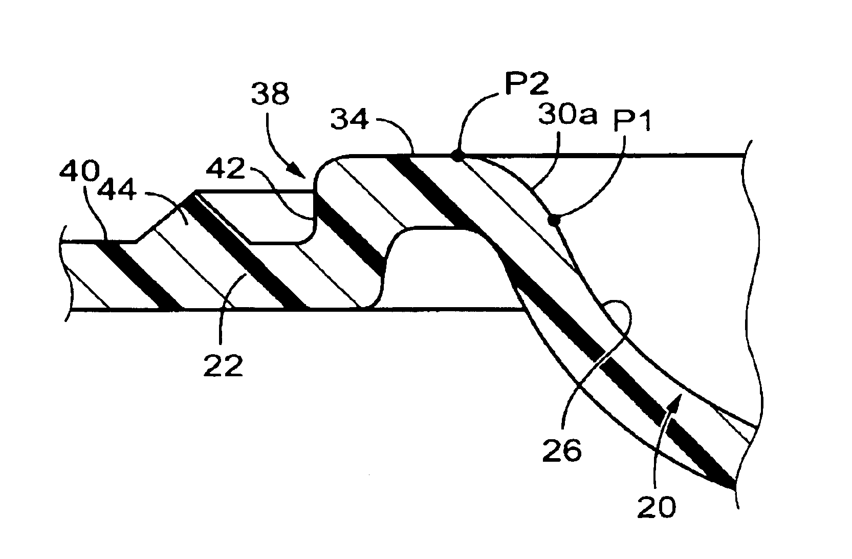
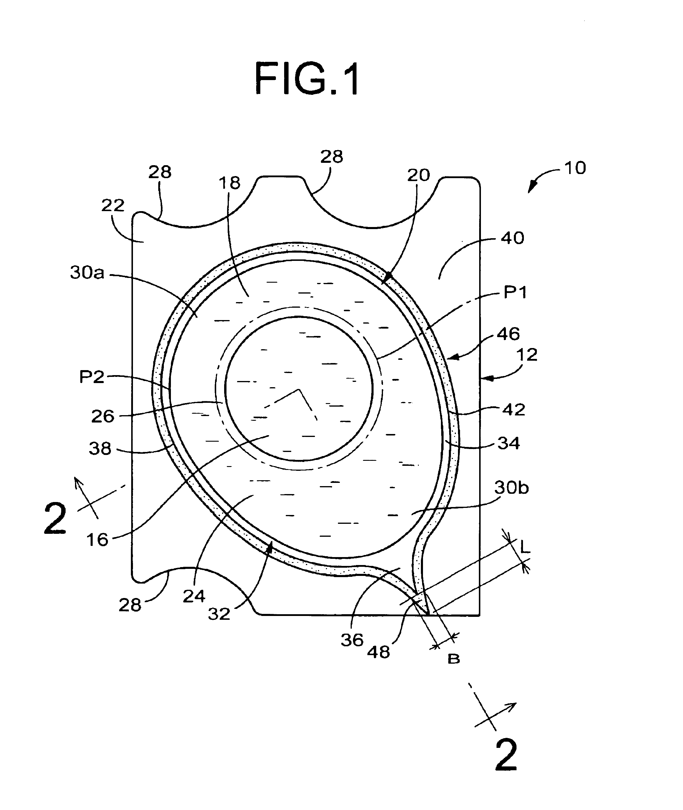
[0054]Referring first to FIGS. 1 and 2, a blister package 10 is shown as the ophthalmic lens storage container of the present invention. The blister package 10 includes a container body 12 and a cover sheet 14. The container body 12 stores a contact lens 16 and a preserving solution 18. The cover sheet 14 is stripably sealed to the container body 12, whereby the contact lens 16 is fluid-tightly enclosed in the container body 12 and can be removed from the container body 12 as needed.

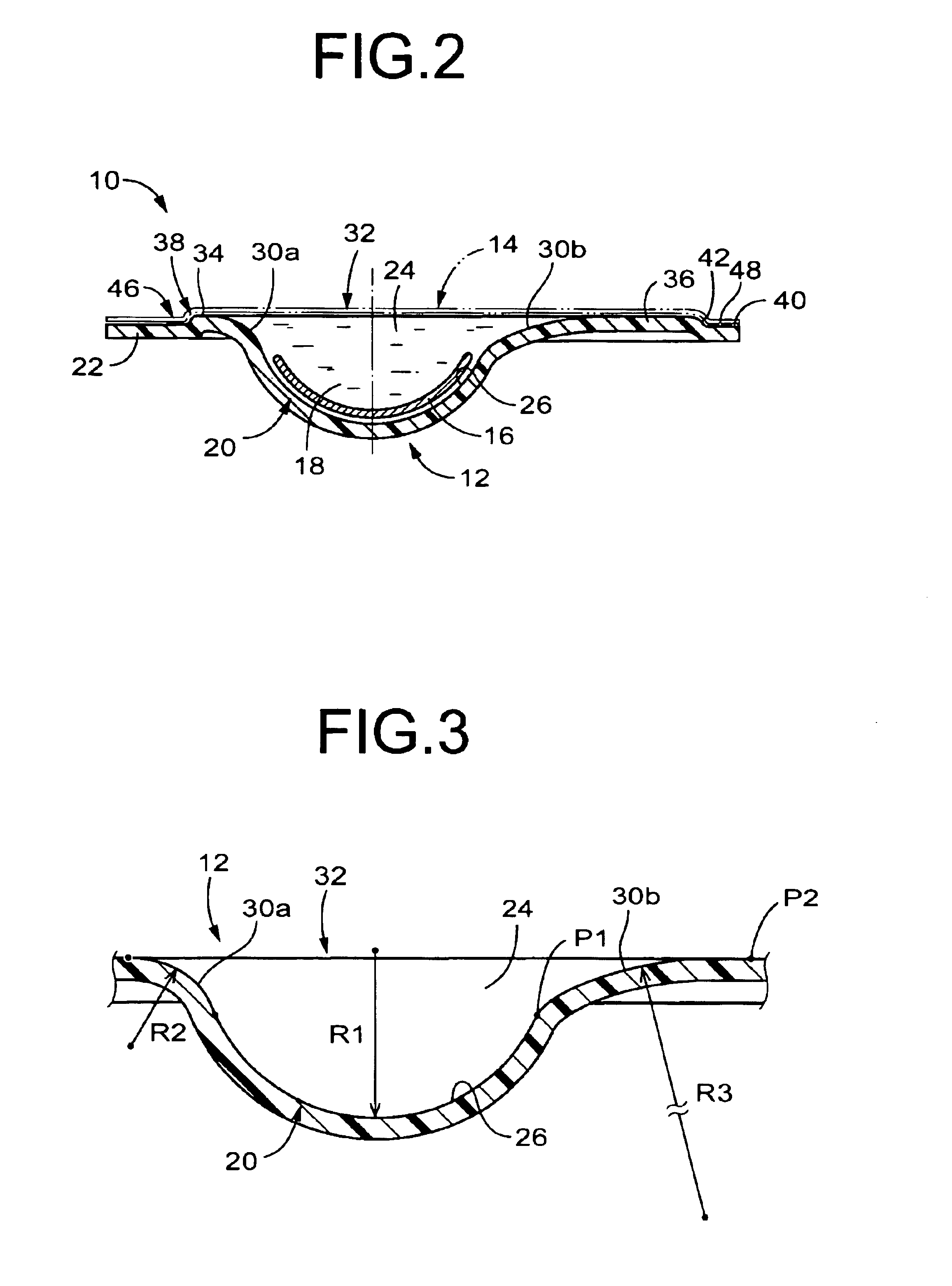
[0055]The container body 12 includes a lens storage portion 20 surrounded by a flange 22, and is formed of a synthetic resin material such as polypropylene and polyethylene by injection molding or the like. The lens storage portion 20 has a semi-spherical shell shape that is made somewhat flat in a thickness direction, and a cavity 24 with a round bottom is formed within the lens storage portion 20. An inner surface of a bottom portion of the lens storage portion 20, i.e., an inner surface of a central p...

second embodiment

[0084]In the illustrated second embodiment, the shape and sizes of the beak-like portion 48 of the sealing zone 46 is not particularly limited, but may be preferably determined or adjusted with materials, shapes, and sizes or other suitable parameters of the container body 12 and the cover sheet 14 taken into consideration. Some examples of the beak-like portions adoptable in the present invention will be described in conjunction with FIGS. 13-15.

[0085]FIG. 13 shows a beak-like portion 84 formed in one circumferential portion of the sealing zone 46 designated as an intended stripping start point, where the ratio B / L is determined to satisfy the following inequality, 186 formed in one circumferential portion of the sealing zone 46 designated as an intended stripping start point, where the ratio B / L is determined to satisfy the following inequality, 288 formed in one circumferential portion of the sealing zone 46 designated as an intended stripping start point, where the ratio B / L is ...

eighth embodiment

[0114]Like the eighth embodiment, the groove 104 functioning as the insulating portion is formed on the flange 22, to be located radially outward of the open-end peripheral portion of the cavity 24, and to extend in the circumferential direction continuously to thereby surround the cavity 24. The groove 104 includes the shoulder surface 42a, 42b, the base portion 130 and the smaller groove 132, 132, likewise. The shoulder surface 42 located on the side of the cavity 24 is partially defined by the outer peripheral portion of the bottom wall 26. Thus, the sealing zone 46 at which the cover sheet 14 is sealed to the container body 12 is set to the base portion 130 housed within the groove 104.

[0115]While the presently preferred embodiment of the invention has been described above in detail for illustrative purpose only, it is to be understood that the invention is not limited to the details of the illustrated embodiment, but may be otherwise embodied.

[0116]For instance, the container b...


PUM

PropertyMeasurementUnit
circumferenceaaaaaaaaaa
radius of curvatureaaaaaaaaaa
shapeaaaaaaaaaa

Abstract

Disclosed is an ophthalmic lens storage container comprising: a container body including a lens storage portion having a cavity for storing a lens and a preserving solution, and a flange surrounding the cavity; and a cover sheet stripably sealed to the flange in a sealing zone that extends around the cavity to thereby fluid-tightly seal the lens storage portion. The flange of said container body includes an insulating portion located radially outward of an open-end peripheral portion of the cavity, extending circumferentially and includes a shoulder surface that extends in a first direction opposite to a second direction along which the cavity is exposed, and the sealing zone is located radially outward of the insulating portion of the flange.

Description

INCORPORATED BY REFERENCE[0001]The disclosure of Japanese Patent Application No. 2001-217080 filed on Jul. 17, 2001 including the specification, drawings and abstract is incorporated herein by reference in its entirety.BACKGROUND OF THE INVENTION[0002]1. Field of the Invention[0003]The present invention relates generally to ophthalmic lens storage containers each having a lens storage portion for storing an ophthalmic lens such as a contact lens, more particularly to such an ophthalmic lens storage container having a novel structure to facilitate removal of the ophthalmic lens from the lens storage portion.[0004]2. Description of the Related Art[0005]A blister package is known as one type of a container for storing a contact lens. JP-A-7-322911, JP-A-9-23916, JP-A-10-313928 and U.S. Pat. No. 6,050,398 disclose known examples of the blister package that includes: a package body having a generally semi-spherical cavity and a flange extending radially outward around the periphery of th...

Claims


Application Information

Patent Timeline
Patent Type & Authority Patents(United States)
IPC IPC(8): B65D77/20B65D77/10A45C11/04B65D75/36B65D81/24
CPCB65D77/2032B65D77/2036B65D2585/545
Inventor ICHIKAWA, SEIICHIOYAMA, HIROYUKITANAKA, MASAYOSHI
Owner MENICON CO LTD
Why Eureka
Try Eureka