Directed spray mast

a technology of spraying mast and spraying device, which is applied in the direction of spraying apparatus, cleaning process and apparatus, chemical equipment and processes, etc. it can solve the problems of large cumbersome unit, device, remote guided, and significant contamination of specific areas within the reaction vessel, so as to prevent crushing or crimping of water or pneumatic lines or cables

Inactive Publication Date: 2005-05-10
SAVANNAH RIVER NUCLEAR SOLUTIONS
View PDF9 Cites 32 Cited by
  • Summary
  • Abstract
  • Description
  • Claims
  • Application Information

AI Technical Summary

Benefits of technology

[0015]A still further advantage of the present invention is that it uses remote actuation of a short elbow of connecting hose so that the flexing required by some of the prior art devices which employ long hoses and cable linkages on the top of a tank or within a vessel is eliminated. In addition, the pneumatic tube and camera cable are enclosed within the cover or support pipe of the invention to protect them from snagging or catching on protrusions within a tank. Crushing or crimping the water or pneumatic lines or cables is prevented.
[0016]All of these features and advantages are found in the present invention which, in another aspect, is a directed spray mast for cleaning identified or selected surface areas in the interiors of closed vessels, pipes, and the like through access ports of relatively small diameters comprising: a multi-positionable, rotatable mast support pipe having upper and lower ends, said pipe having a substantially uniform diameter for insertion into an access port of a vessel to be cleaned; lift bail means for supporting and vertically and radially positioning said mast pipe by rotating same; a water supply pipe coaxially disposed within said support pipe and extending above and below said support pipe; a spray nozzle assembly pivotally mounted to a support plate carried by said water pipe at said pipe's lower end, said assembly extending with and being parallel to said support pipe in its compact, closed position; a submersible video camera mounted in said nozzle assembly; and pneumatic means having one end pivotally mounted to the said support pipe adjacent its lower end with its other end being pivotally attached to said nozzle assembly for raising and lowering the nozzle assembly in response to actuation of the pneumatic means whereby the nozzle assembly is caused to swing outwardly from said support plate to an expanded position of the spray mast and, with camera guidance, the nozzle assembly can be raised, lowered, and rotated to direct water spray to selected interior areas of the vessel to be cleaned.
[0017]The invention includes enclosing the pneumatic lines for actuating the pneumatic means and the camera cable within the support pipe to protect same and to provide for easy insertion and removal of the directed spray mast from an access port. A pneumatic pressure pump with control valves are connected to said lines as is known to those skilled in the art. Likewise, the camera cable is connected to a video display monitor and the supply pipe is connected to a controllable source of high pressure water.
[0018]Still another feature of the present invention is that the spray mast can be made in differing lengths for deep vessels or extended pipe lengths. These and other features and advantages of the invention will be appreciated from the drawings and detailed description that follow.

Problems solved by technology

Most often, specific areas within a reaction vessel get significantly contaminated whereas other areas may have no contamination at all.
Evaporators, boilers, and heat exchange equipment almost invariably leave deposits behind that require removal.
However, removal of the cell cover from the base of the cell means that the cleaning liquid which may be sprayed up against the bottom of the cell cover will have to be collected and an additional area will have to be cleaned.
However, the use of this cleaning apparatus requires a large man-way opening and multiple cantilevered arms which spray the entire surface inside a vessel leaving a large quantity of waste water.
However, again, this device, though remotely guided, is a large cumbersome unit that can be used only where a manway is available.

Method used


Image

  • Directed spray mast
  • Directed spray mast
  • Directed spray mast

Examples


Embodiment Construction

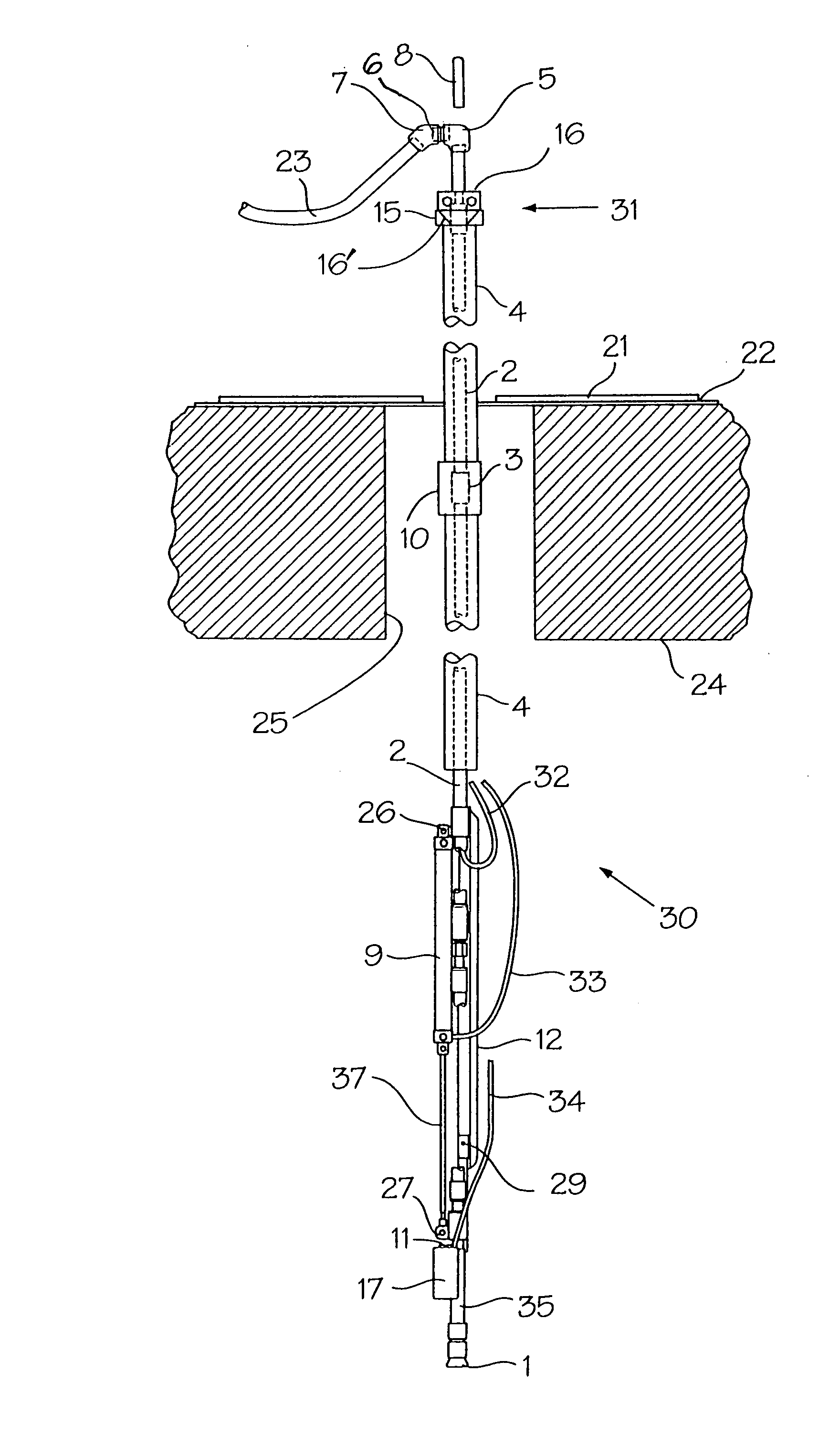
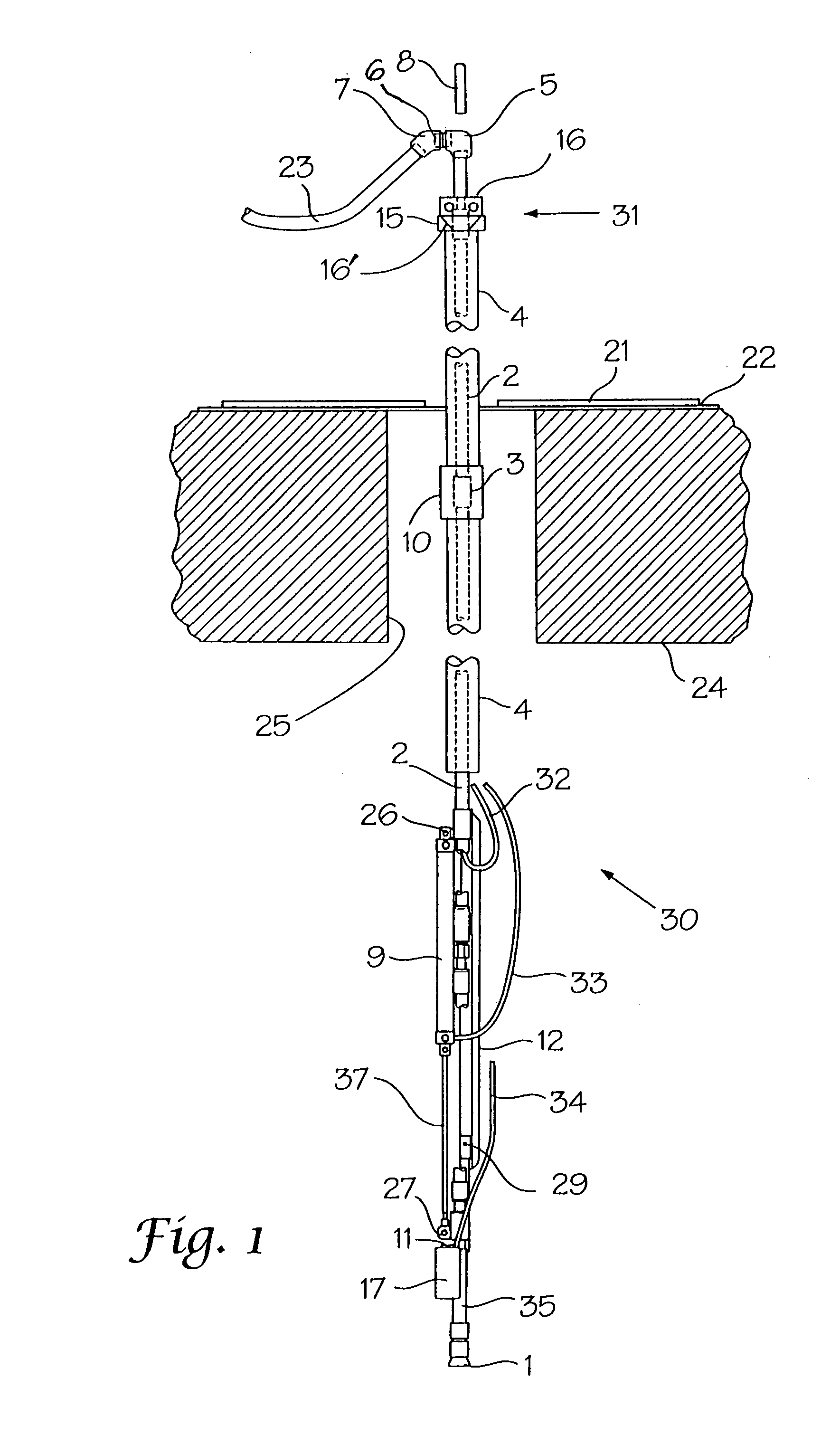
[0024]For convenience, the embodiments and claims refer to the invention in a vertical position; but, horizontal or other positions are within the scope of the invention.

[0025]Referring first to FIGS. 1 and 1a, directed spray mast 30 is shown positioned in access port 25 which is formed in wall 24 of a tank or containment vessel. In this position, the mast 30 is held by the bail connector 8 (FIG. 1a). Conveniently, a crane may be used to raise, lower, and hold the spray mast. Cover plate 21 surrounds the mast 30 to cover the opening to the access port 25 and rubber gasket 22 is positioned around mast pipe 4 and extends outwardly as a seal between the cover plate and the vessel wall (FIG. 1. This) cover plate prevents back spray from leaving the vessel during a cleaning operation.

[0026]Spray mast 30 comprises the support mast pipe 4 or the outer protective cover or jacket of the upper portion of the directed spray mast. This pipe may have a diameter of ¾″ in a preferred embodiment. ...


PUM


Abstract

Disclosed is an elongated, tubular, compact high pressure sprayer apparatus for insertion into an access port of vessels having contaminated interior areas that require cleaning by high pressure water spray. The invention includes a spray nozzle and a camera adjacent thereto with means for rotating and raising and lowering the nozzle so that areas identified through the camera may be cleaned with a minimum production of waste water to be removed.

Description

CROSS REFERENCE TO RELATED APPLICATION[0001]This application claims priority of Provisional Application Ser. No. 60 / 455,303, filed Mar. 17, 2003.[0002]The invention was made with Government support under Contract No. DE-AC09-96-SR18500 awarded by the United States Department of Energy. The Government has certain rights in the invention.FIELD OF THE INVENTION[0003]This invention relates to high pressure cleaning devices for the interiors of vessels or tanks which are used for storage or for industrial processes. More specifically, this invention relates to high pressure cleaning devices that can gain access to the interior of a vessel through a relatively narrow port and clean only identified contaminated areas so that a minimum volume of contaminated water or solvent is generated.BACKGROUND OF THE INVENTION[0004]In many industrial processes tanks or vessels are employed which are used either to store liquids for future use or in part of a process. Also, many types of vessels are use...

Claims


Application Information

Patent Timeline
Patent Type & Authority Patents(United States)
IPC IPC(8): B08B9/04B08B9/08B08B9/093B08B9/02B05B15/06
CPCB05B15/061B08B9/093B08B9/0433B05B15/62
Inventor NANCE, THOMAS A.SIDDALL, ALVIN A.CHENG, WILLIAM Y.COUNTS, KEVIN T.
Owner SAVANNAH RIVER NUCLEAR SOLUTIONS
Why Eureka
Try Eureka