Tire machining tool

a technology of machining tools and cylinder cutting tools, which is applied in the direction of shaping cutters, manufacturing tools, wood boring tools, etc., can solve problems such as superficial heating, and achieve the effect of preventing jamming

Inactive Publication Date: 2005-05-10
MICHELIN RECH & TECH SA
View PDF9 Cites 2 Cited by
  • Summary
  • Abstract
  • Description
  • Claims
  • Application Information

AI Technical Summary

Benefits of technology

[0008]The present invention relates to an improved cylindrical cutting tool which automatically ensures that the strip of cut material is divided into portions in order to prevent jamming.
[0011]Production of the notches by machining grooves on the sharp cutting edge side of the tool has the advantage of allowing strict maintenance of the profile of the notches during successive sharpening operations of the cutting edge.

Problems solved by technology

WO 00 / 15388), but this process causes superficial heating which it is sometimes desirable to avoid.
In the case of a heavy goods vehicle tire, with longitudinal ribs, the length of the strip may reach several meters and even exceed meters, which poses discharge problems and may also cause jams.

Method used


Image

  • Tire machining tool
  • Tire machining tool
  • Tire machining tool

Examples


Embodiment Construction

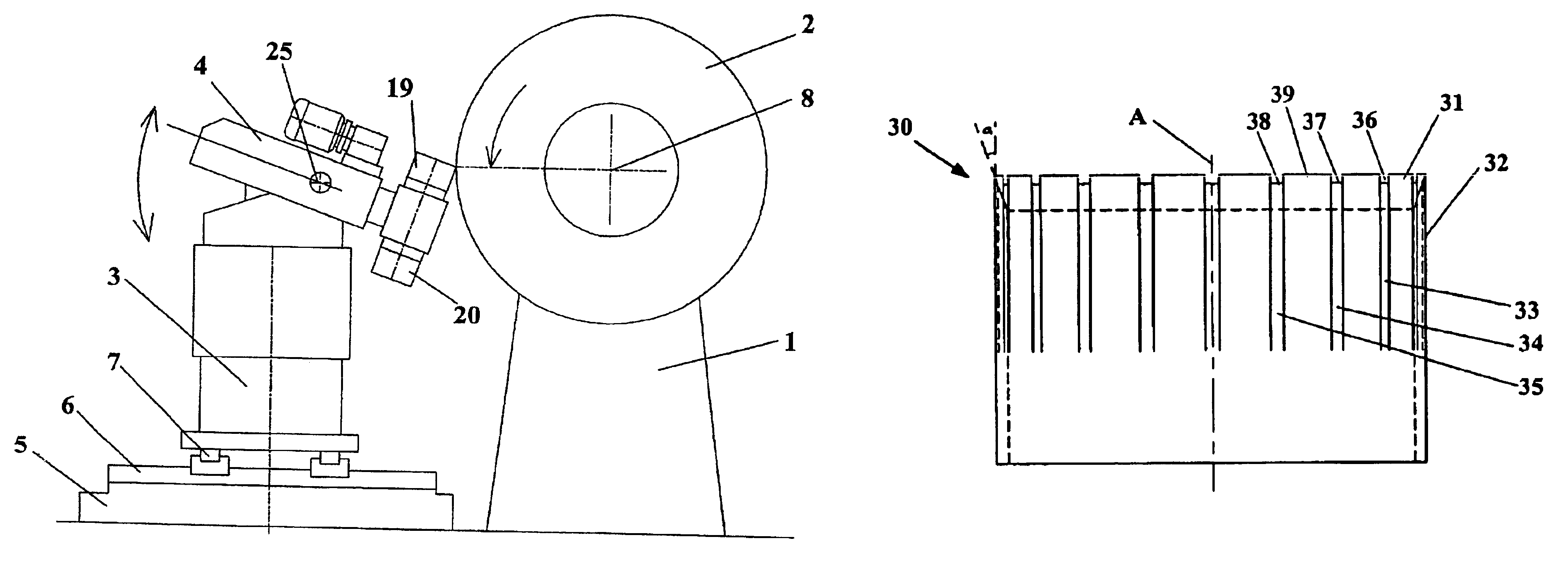
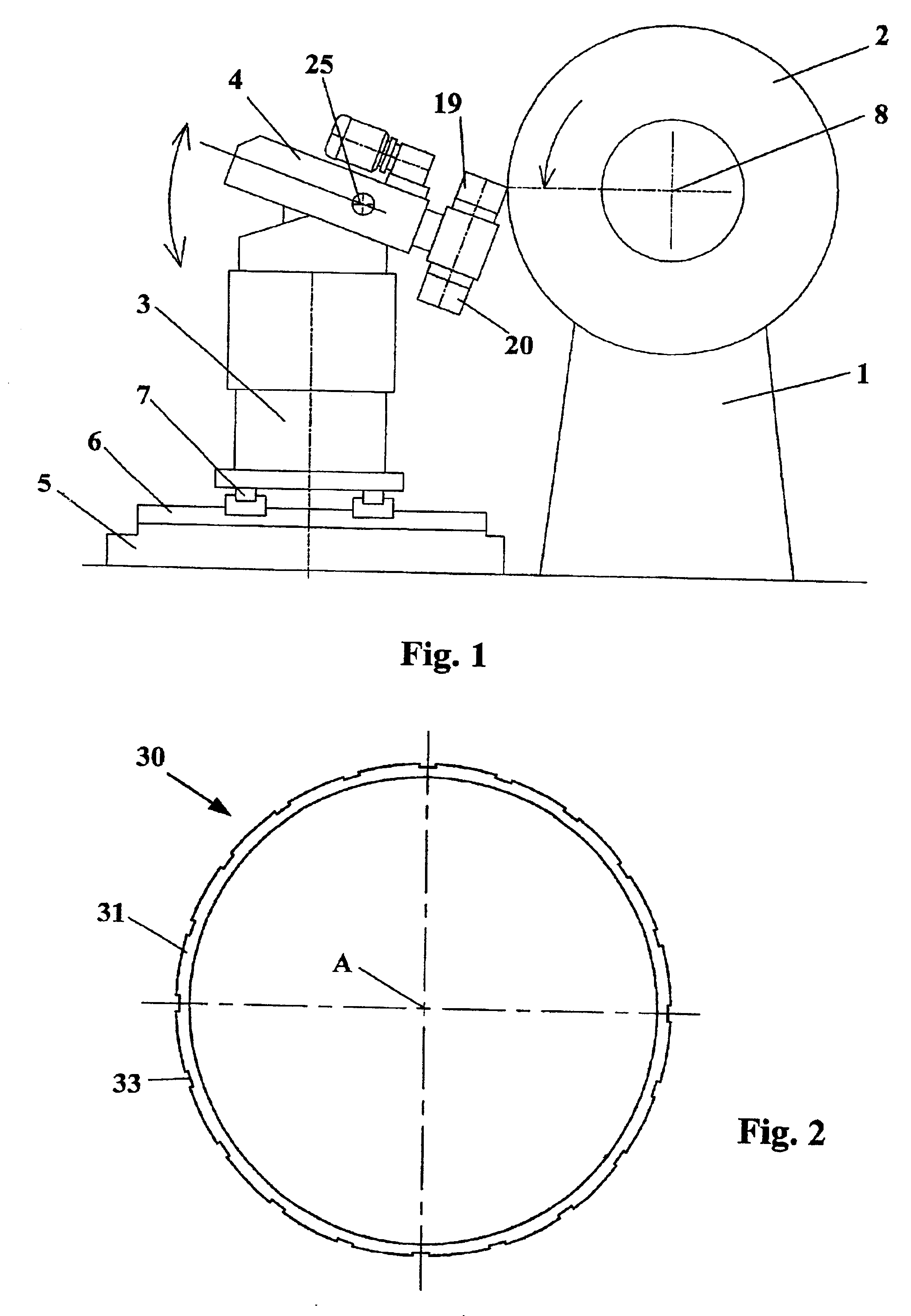
[0026]FIG. 1 is a highly schematic view of a machine for machining tire treads comprising a cutting tool according to the invention. The machine comprises a first fixed frame 1 supporting a drum (not shown) on which is mounted a tire 2. The machine also comprises a mobile frame 3 supporting a tool holder 4. The frame 3 is mounted on a fixed base 5 by means of two pairs of horizontal rails 6 and 7. The rails 6 are oriented perpendicularly to the axis of rotation 8 of the tire and permit translational movement of the frame 3 towards or away from the tire 2. The rails 7 are oriented parallel to the axis of rotation 8 of the tire and permit translational displacement of the frame 3 parallel to the axis of rotation of the tire 2. The combination of these two translational movement allows the cutting tool to follow all the conventional tire profiles. The frame 3 also allows vertical displacement of the tool holder 4, due to conventional means which are not shown. The machine additionally ...


PUM

PropertyMeasurementUnit
diameteraaaaaaaaaa
diameteraaaaaaaaaa
angleaaaaaaaaaa

Abstract

A cylindrical cutting tool for a tire detreading or machining machine, the circular blade of which has a beveled cutting edge, wherein the cutting edge is interrupted by at least one notch, that is to say a portion having a lower axial height than the cutting edge.

Description

BACKGROUND OF THE INVENTION[0001]1. Technical Field of the Invention[0002]The present invention relates to a tool for machining viscoelastic products; more precisely, it relates to a cylindrical cutting tool for a machine for detreading and machining rubber products such as tires.[0003]2. The Related Art[0004]Tires are known to comprise a tread consisting of an outer layer of rubber-based mixtures, of greater or lesser thickness, in which are molded various grooves and tread patterns intended, inter alia, to improve the vehicle's grip relative to the ground.[0005]In certain cases, it is necessary to machine the outer surface of the tire: for example, to prepare for retreading of a worn tire or, indeed, to obtain a “worn” tire from a new tire, with a view to performing certain tests on the rigid belt, or on the carcass, without being hampered by the very considerable heating associated with the thickness of the rubber of the new tread during the tests.[0006]In the first case (retread...

Claims


Application Information

Patent Timeline
Patent Type & Authority Patents(United States)
IPC IPC(8): B26D1/01B26D1/00B26D1/44B29D30/68
CPCB26D1/44B26D3/003Y10T407/20Y10T409/309296Y10T407/1966Y10T408/89
Inventor TROCHON, FRANCOIS
Owner MICHELIN RECH & TECH SA
Why Eureka
Try Eureka