Stent delivery system

Inactive Publication Date: 2005-05-10
CR BARD INC
View PDF21 Cites 67 Cited by
  • Summary
  • Abstract
  • Description
  • Claims
  • Application Information

AI Technical Summary

Benefits of technology

[0014]According to the present invention, pinch zones interact in the last stages of sheath withdrawal. This raises frictional resistance, but from a low level. The pinching effect enhances gripping of the stent when enhanced gripping is needed, however not before then.
[0015]With the invention, it will be noted, there is no interaction of the pinch zone on the sheath and the pinch zone on the catheter until after a majority of the length of the stent has already been released. Thus, the pinch zones do not materially add to the sliding resistance during release of the stent, until the last part of the release process. During this last part of the release process, the amount of sliding resistance is less than the frictional resistance at the start of the release process so that there i

Problems solved by technology

Thus, the likelihood of an uncontrolled spring of the stent away from the deliver

Method used


Image

  • Stent delivery system
  • Stent delivery system

Examples


Example

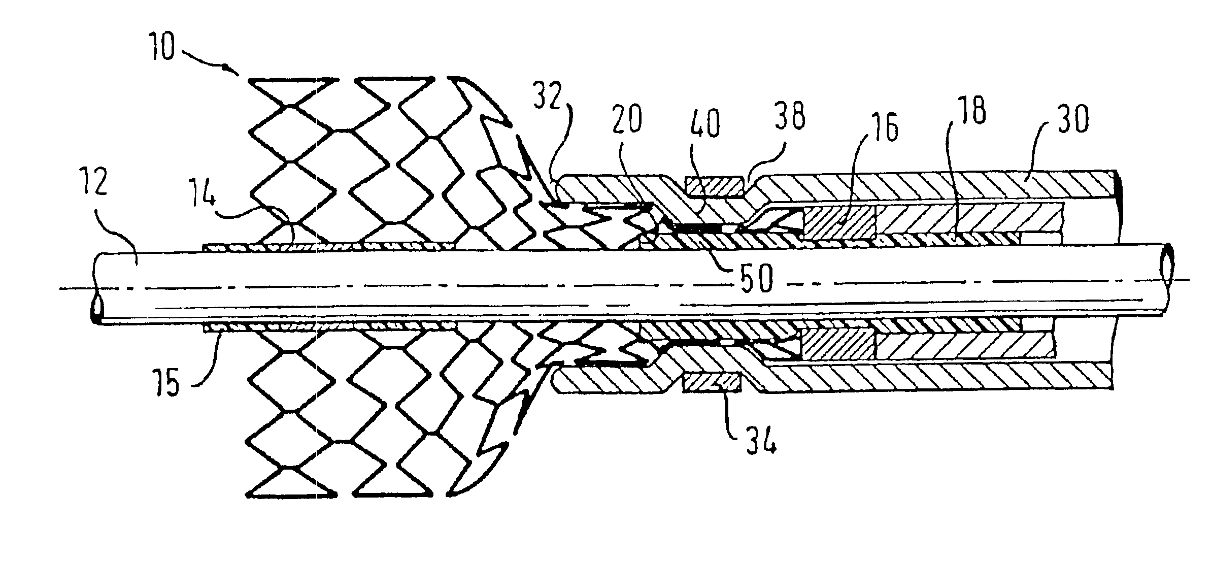
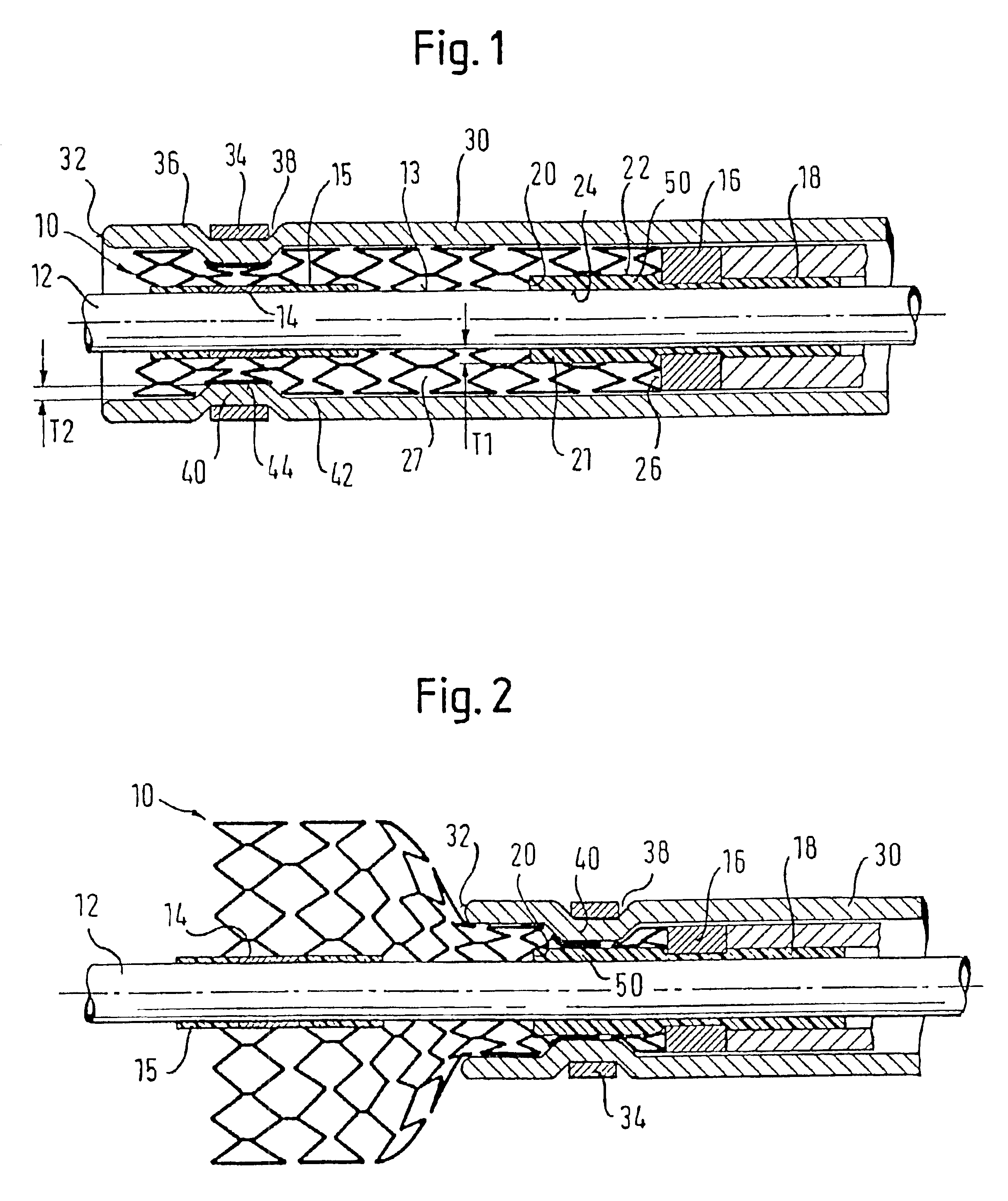
[0021]FIG. 1 shows a delivery system for a stent 10. The system is based on a tubular catheter tube 12, designed to be advanced along a guidewire (not shown). The catheter tube carries on its cylindrical surface 13 a distal marker 14, retained axially in position on the tube 12 by a short length of polymeric material 15 melted onto the tube 12. A proximal marker band 16 is retained on the tube 12 in a cured annular bed 18 of polymeric adhesive. This adhesive bed extends distally of the marker band 16 as far as a distal end 20 to form a short cylindrical length 21 of the cured adhesive, distal in relation to the marker band 16, with a radially outwardly facing surface 22 and a radially inwardly facing surface 24 bonded to the cylindrical surface of the tube 12. This cylindrical zone, radially between cylindrical surfaces 22 and 24, has a radial thickness T1. Reference is made to the fact that the marker band 16 provides a distal-facing end surface 26 which defines the proximal end of...


PUM


Abstract

The present invention relates to a stent delivery system comprising a catheter tube defining for a self-expanding stent a bed having a length direction in line with the catheter length, a radially outward facing stent-receiving surface, a distal end at or near the distal end of the catheter and a proximal end spaced proximally from the distal end; an outer catheter tube to circumferentially surround the bed; and the outer tube being arranged to be withdrawn proximally to release the self-expanding stent radially outwardly from the bed; and further comprising: on the stent receiving bed surface, immediately distal of the proximal end of the bed, a first pinch zone; on the outer tube, at or near a distal end thereof, and on its radially inwardly facing surface, a second pinch zone; the first and second pinch zones facing each other when the distal end of the outer tube is not quite fully withdrawn proximally, relative to the bed; the facing of the opposed first and second pinch zones defining a reduced-width annulus for pinching the proximal end of the stent to make available increased resistance to relative axial movement between the stent and the catheter shaft just prior to full withdrawal of the outer tube.

Description

RELATED APPLICATION[0001]This application is a continuation of application Ser. No. 09 / 637,617 filed Aug. 11, 2000 now U.S. Pat. No. 6,517,547.BACKGROUND OF THE INVENTION[0002]1) Field of the Invention[0003]In the context of this specification, a stent is a support structure, more or less tubular, for placement within a bodily lumen to support the tissue walls of the lumen. These stents usually require a delivery system to bring them to precisely the desired position within the body of the patient. This invention relates to stent delivery systems.[0004]Two broad categories of stent can be identified. In one category, the stent is fitted around a sausage-shaped balloon, the balloon itself being on the distal end of a catheter. The catheter is advanced, for example, in the arterial system of the patient to the location where the stent is to be placed, and the balloon is then inflated to deform the stent plastically, expanding the stent radially against the wall of the bodily lumen. Si...

Claims


Application Information

Patent Timeline
IPC IPC(8): A61F2/06A61F2/95A61F2/966
CPCA61F2/966A61F2/95
Inventor FEESER, JOERGSCHENDZIELORZ, LARS
Owner CR BARD INC
Why Eureka
Try Eureka