Vehicle control system and control method

Inactive Publication Date: 2005-05-10
NISSAN MOTOR CO LTD
View PDF25 Cites 34 Cited by
  • Summary
  • Abstract
  • Description
  • Claims
  • Application Information

AI Technical Summary

Benefits of technology

[0006]In order to cope with such situations, particularly, it is thought that, in a structure wherein the vehicle is comprised of the electric power generator, the secondary battery unit and the vehicle drive motor which is driven by electric power output supplied from at least one of the electric power generator and the secondary battery unit, electric power output or a capacity of the secondary battery unit is preset to have a large value so as to cope with power output of the motor. But, such a structure is reflected in an increase in a capacity or weight of the secondary battery unit, with a resultant degraded fuel consuming performance of the vehicle while undesirably causing an inability to efficiently use a volume of a vehicle compartment.
[0007]The present invention has been made based on the above studies and has an object to provide a control system and a control method for a vehicle which enables similar qualities of accelerating operation, i.e. similar qualities of torque response characteristic to be obtained at all times to preclude an operating characteristic from being suffered with a differential feeling regardless of the electric power generator operating conditions or the engine operating conditions, such as whether or not an electric power generator or an engine remains in a stop condition, and a capacity of the secondary battery unit.
[0008]According to an aspect of the present invention, there is provided a control system for a vehicle having an electric power generator, an electric power storage unit, a drive motor driven by electric power supplied from at least one of the electric power generator and the electric power storage unit, and drive wheels driven by drive power supplied from the drive motor. More specifically, the control system is provided with: a demanded drive power calculating section calculating a demanded drive power required for driving the vehicle; an allowable drive electric power output calculating section calculating allowable drive electric power output of the electric power storage unit required for compensating a delayed response of the electric power generator with respect to a variation in the demanded drive power; an available electric power output calculating section calculating available electric power output of the electric power storage unit to be outputted on the basis of a state of charge of the electric power storage unit, the available electric power output being electric power outputable from the electric power storage unit; and a target electric power output calculating section calculating target electric power output to be produced from the electric power generator on the basis of the demanded drive power, the allowable drive electric power output of the electric power storage unit and the available electric power output of the electric power storage unit. Resultantly, the control system controls the electric power storage unit on the basis of the allowable drive electric power output and the available electric power output, and the electric power generator on the basis of the target electric power output so as to control the vehicle correspondingly to the demanded drive power.
[0009]According to another aspect of the present invention, there is provided a control system for a vehicle having an electric power generator, an electric power storage unit, a drive motor driven by electric power supplied from at least one of the electric power generator and the electric power storage unit, and drive wheels driven by drive power supplied from at least one of the engine and the drive motor the drive motor. More specifically, the control system is provided with: a demanded drive power calculating section calculating a demanded drive power required for driving the vehicle; an allowable drive electric power output calculating section calculating allowable drive electric power output of the electric power storage unit requir

Problems solved by technology

But, such a structure is reflected in an increase in a capacity or weight of the secondary battery unit, with a resultant degraded f

Method used


Image

  • Vehicle control system and control method
  • Vehicle control system and control method
  • Vehicle control system and control method

Examples


second preferred embodiment

[0091]Now, a detailed description will be given to a vehicle control system of a second preferred embodiment of the present invention which is able to stop the operation of the electric power generator 101 at a given instance.

[0092]The vehicle control system of the second preferred embodiment has the same structure as that of the first preferred embodiment and, therefore, a detailed description of the same is herein omitted. Also, the vehicle control system of the second preferred embodiment executes the same steps up to step S8 shown in FIG. 4 and, thus, a detailed description of these steps is herein omitted except for remaining steps which will be discussed with reference to a flow chart of FIG. 13.

[0093]In FIG. 13, in step S21, the allowable drive electric power output PA is read out. In the presently described preferred embodiment, The allowable drive electric power output PA involves a steady state allowable drive electric power output PA1 determined for the stop condition of ...

third preferred embodiment

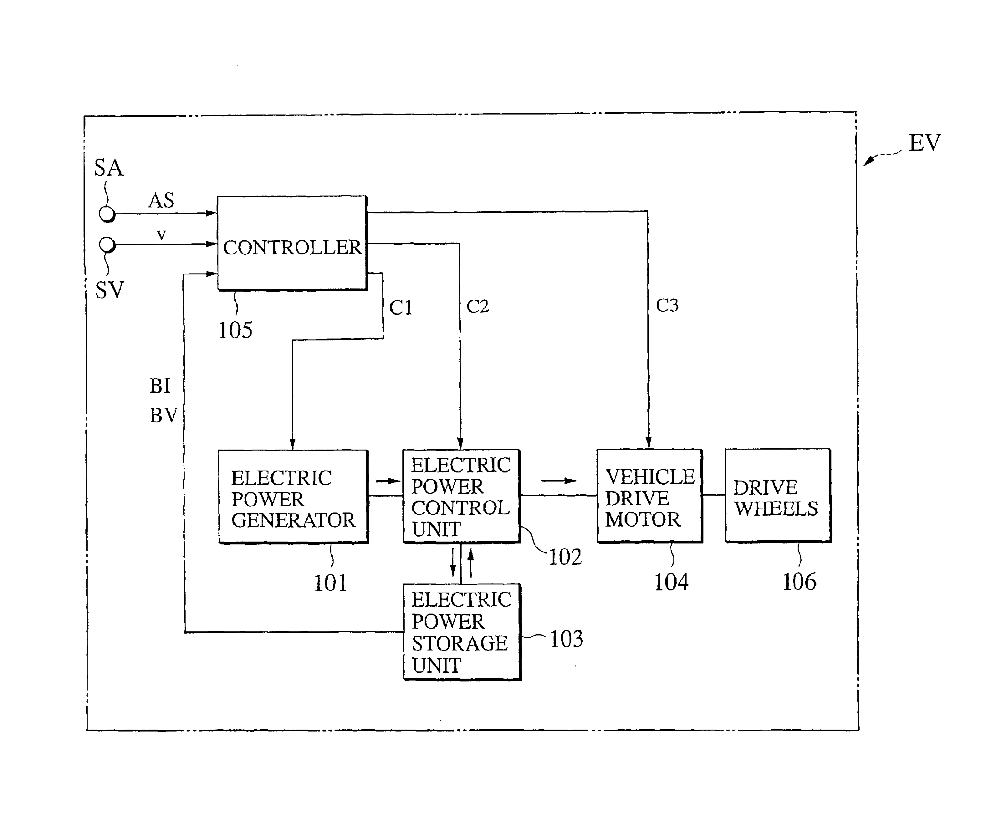
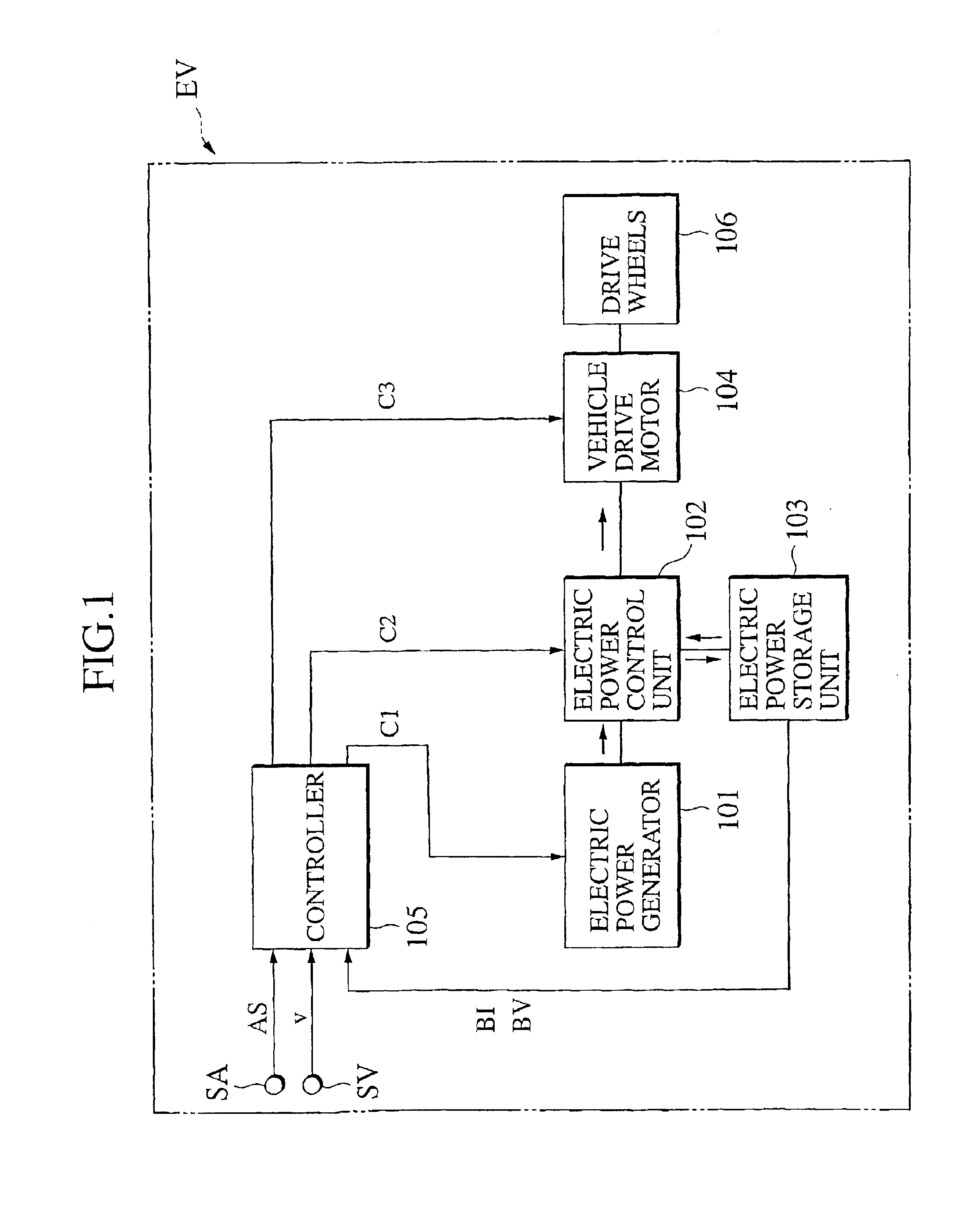
[0103]FIG. 14 shows a structural overview of a vehicle EV to which a vehicle control system of a third preferred embodiment of the present invention is applied, with the vehicle being exemplarily shown as a so-called parallel hybrid vehicle with drive wheels driven by an engine and a drive motor. In the so-called parallel hybrid vehicle used in the present preferred embodiment, the vehicle drive source is comprised of the engine and the drive motor whereas, in the first preferred embodiment, the drive source is comprised only of the drive motor. Thus, replacing the electric power generator with the engine enables the present invention to be similarly described in principle. Also, the same component parts bear the same reference numerals as those used in the first preferred embodiment of FIG. 1 to suitably omit the redundant description.

[0104]In FIG. 14, the drive power produced by the engine 107 is transmitted to the drive wheels 106 via a transmission 108. An electric power generat...

fourth preferred embodiment

[0138]Now, a description is given to a vehicle control system of a fourth preferred embodiment of the present invention which enables a stop in the engine 107 at a given state.

[0139]The structure of the presently described preferred embodiment is similar to that of the third preferred embodiment and, therefore, a detailed description of the same is herein omitted. Since, also, the operation is identical to that which involves steps up to step S37 shown in FIG. 16 which is referred to in the third preferred embodiment, the description of the same is omitted and the operation subsequent to that step will be described with reference to the flow chart of FIG. 19.

[0140]In FIG. 19, in step S51, the allowable drive electric power output PA is read out. In the presently described preferred embodiment, the allowable drive electric power output is composed of the steady state allowable drive electric power output PA1 during the stop condition of the engine 107 and the allowable drive electric...


PUM


Abstract

A control system for a vehicle, having drive sections (104, 107, 109), a power supply section (101, 103, 107, 109) including an electric power storage unit to supply power to the drive section, includes a demanded power calculating section (1) calculating a demanded drive power required for driving the vehicle, an allowable drive electric power output calculating section (2) calculating allowable drive electric power output of the electric power storage unit necessary for compensating a delayed response of the power supply section with respect to a variation in the demanded power, an available electric power output calculating section (3) calculating available electric power output of the electric power storage unit on the basis of a stage of charge of the electric power storage unit, and a target power calculating unit (4, 7, 9) calculating target power to be produced by the power supply section on the basis of the demanded drive power, allowable drive electric power output and available electric power output.

Description

TECHNICAL FIELD[0001]The present invention relates to a control system and a control method for a vehicle and, more particularly, to a control system and a control method for an electric vehicle or a hybrid vehicle having an electric power generator, an electric power storage unit, and a vehicle drive motor driven by electric power output supplied from at least one of the electric power generator and the electric power storage unit.BACKGROUND ART[0002]An electric vehicle or hybrid vehicle incorporates not only an electric power storage unit such as a secondary battery unit but also an electric power generator which is driven by a fuel cell or an engine. With such a structure, merely replenishing fuel to the fuel cell or the engine as in a fuel replenishing in a general vehicle allows the electric power generator to be operated with the fuel cell or the engine such that a user is able to preclude a troublesome charging operation for the electric power storage unit per se.[0003]Japane...

Claims


Application Information

Patent Timeline
IPC IPC(8): B60L11/18B60L15/20B60K6/04B60K6/00B60K6/46B60K6/48B60L50/15B60L50/16B60W10/06B60W10/08B60W10/26B60W20/00
CPCB60K6/32B60L11/005B60L11/14B60L11/16B60L11/1861B60L11/1887B60L15/20B60L15/2045B60W10/08B60W10/26B60K6/48Y02T10/70B60L2240/36B60L2240/421B60L2240/423B60W20/00B60W2510/244B60W2520/10B60W2540/10B60W2710/081B60W2710/083Y02T10/6221Y02T10/7022Y02T10/7044Y02T10/705Y02T10/7077Y02T10/7283Y02T90/34Y02T10/48Y10S903/908Y02T10/642B60L50/16B60L50/30B60L50/40B60L58/15B60L58/40Y02T10/40Y02T10/62Y02T10/64Y02T10/7072Y02T10/72Y02T90/40B60W10/24B60W20/10B60W2710/242
Inventor KAZAMA, ISAMU
Owner NISSAN MOTOR CO LTD
Why Eureka
Try Eureka