Mounting structure of fuse connection terminals on board

a technology of mounting structure and fuse connection, which is applied in the direction of electrical apparatus casing/cabinet/drawer, coupling device connection, printed circuit non-printed electric components association, etc., can solve the problems of affecting the reliability of the soldering portion, the fuses cannot be precisely mounted on the board, and the time and labor required to achieve the effect of convenient fixing to the circuit board

Inactive Publication Date: 2005-05-10
YAZAKI CORP
View PDF18 Cites 24 Cited by
  • Summary
  • Abstract
  • Description
  • Claims
  • Application Information

AI Technical Summary

Benefits of technology

[0017]In this structure, the support block is fixed by one screw, and therefore the support block can be easily fixed to the circuit board. If the support block is fastened merely by one screw, the position of this support block in the direction of rotation thereof about the screw is not fixed, and therefore there are provided the positioning portions, and besides the positioning portions are disposed point-symmetrically with respect to the screw, and therefore the support block can be mounted on the circuit board in a 180 degree-turned manner. Thus, there can be provided the two mounting directions.

Problems solved by technology

However, when many fuses are to be mounted collectively on a specified portion of the circuit board, much time and labor are required for mounting the plurality of connection terminals on the board independently of one another, and besides in some cases, the fuses can not be mounted precisely on the board.
Furthermore, when inserting and withdrawing the fuse relative to the connection terminal, an insertion / withdrawal force acts directly on a soldering portion of the connection terminal, and therefore there is encountered a problem that the reliability of the soldering portion is adversely affected.

Method used


Image

  • Mounting structure of fuse connection terminals on board
  • Mounting structure of fuse connection terminals on board
  • Mounting structure of fuse connection terminals on board

Examples


Embodiment Construction

[0024]A preferred embodiment of the present invention will now be described with reference to the drawings.

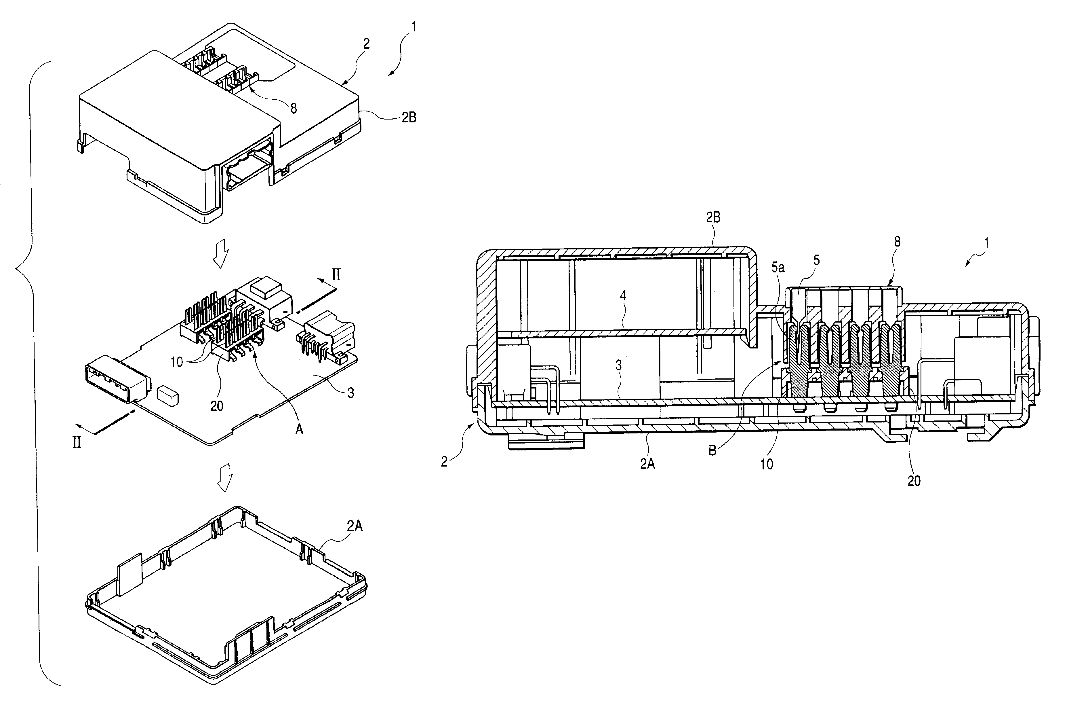
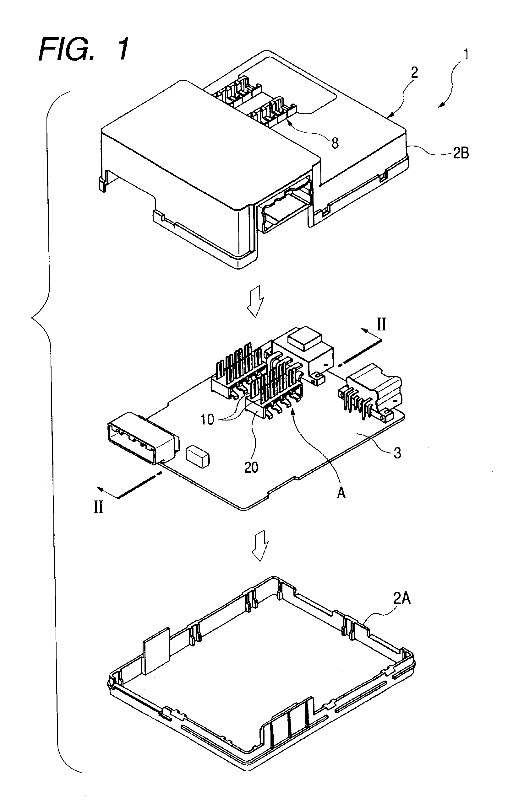
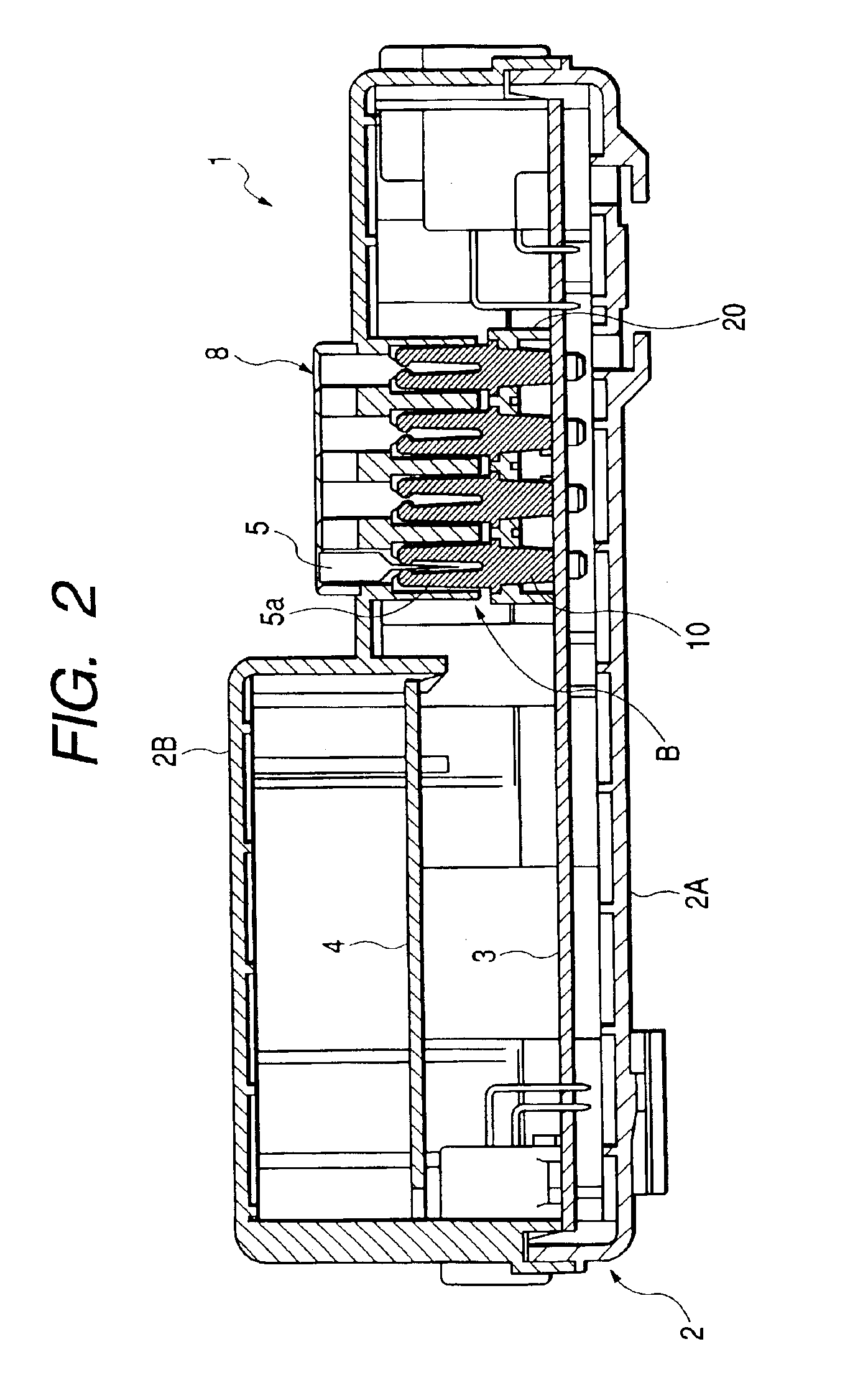
[0025]FIG. 1 is an exploded, perspective view showing one example of an electric connection box incorporating a mounting structure of this embodiment, FIG. 2 is a cross-sectional view taken along the line II—II of FIG. 1, showing the electric connection box in its assembled condition, FIG. 3 is a perspective view showing a condition in which a portion A, shown in. FIG. 1, is in the process of being produced, FIG. 4 is an exploded, perspective view of the portion A of FIG. 1, FIG. 5 is an enlarged view of a portion B shown in FIG. 2, and FIG. 6 is a cross-sectional view taken along the line VI—VI of FIG. 4.

[0026]As shown in FIGS. 1 and 2, this electric connection box 1 comprises a casing 2 (which is made of a resin), consisting of a lower casing 2A and an upper casing 2B, and two (first and second) circuit boards 3 and 4 contained in the casing 2. The first circuit board 3 is fi...


PUM


Abstract

A plurality of fuse connection terminals (10), each having at one end an insertion portion (11) for the insertion of a fuse terminal, and having at the other end a soldering portion (12) for connection to a circuit board (3), are press-fitted and fixed to a support block (20) at their intermediate portions thereof disposed between the insertion portion (11) and the soldering portion (12). Then, the support block (20) is fixedly secured to the circuit board (3), and the soldering portions (12) of the connection terminals (10) are soldered to the circuit board (3). A crank-shaped bent portion (18) is provided between the press-fitting portion (13) and the soldering portion (12), and projections (14, 15) for transmitting a withdrawal force and an insertion force to the support block (20) are formed respectively at front and rear ends of the press-fitting portion (13).

Description

[0001]The present application is based on Japanese Patent Application No. 2002-8976, the entire contents of which are incorporated herein by reference.BACKGROUND OF THE INVENTION[0002]1. Field of the Invention[0003]This invention relates to a mounting structure of fuse connection terminals (which are used for connecting fuses to a circuit board) on the circuit board.[0004]2. Related Art[0005]When fuses are to be mounted on a circuit board, there is, in many cases, used a method in which first, connection terminals (fuse connection terminals), used for connecting the fuses to a circuit board, are soldered to the circuit board, and terminals of the fuses are inserted respectively into insertion portions of these connection terminals, thereby connecting the fuses to the connection terminals.[0006]However, when many fuses are to be mounted collectively on a specified portion of the circuit board, much time and labor are required for mounting the plurality of connection terminals on the ...

Claims


Application Information

Patent Timeline
Patent Type & Authority Patents(United States)
IPC IPC(8): H01H85/00H01H85/20H05K3/30H01H85/34H05K1/18
CPCH01H85/2035H05K3/301H01H85/34H01H2085/2085H01H2085/208
Inventor NAGAOKA, YASUTAKA
Owner YAZAKI CORP
Why Eureka
Try Eureka