

Surface mount antenna, method of manufacturing same, and communication device
- Summary
- Abstract
- Description
- Claims
- Application Information
AI Technical Summary
Benefits of technology
Problems solved by technology
Method used
Image

Examples
Embodiment Construction
[0057]Preferred embodiments of the present invention will now be described with reference to the attached drawings.
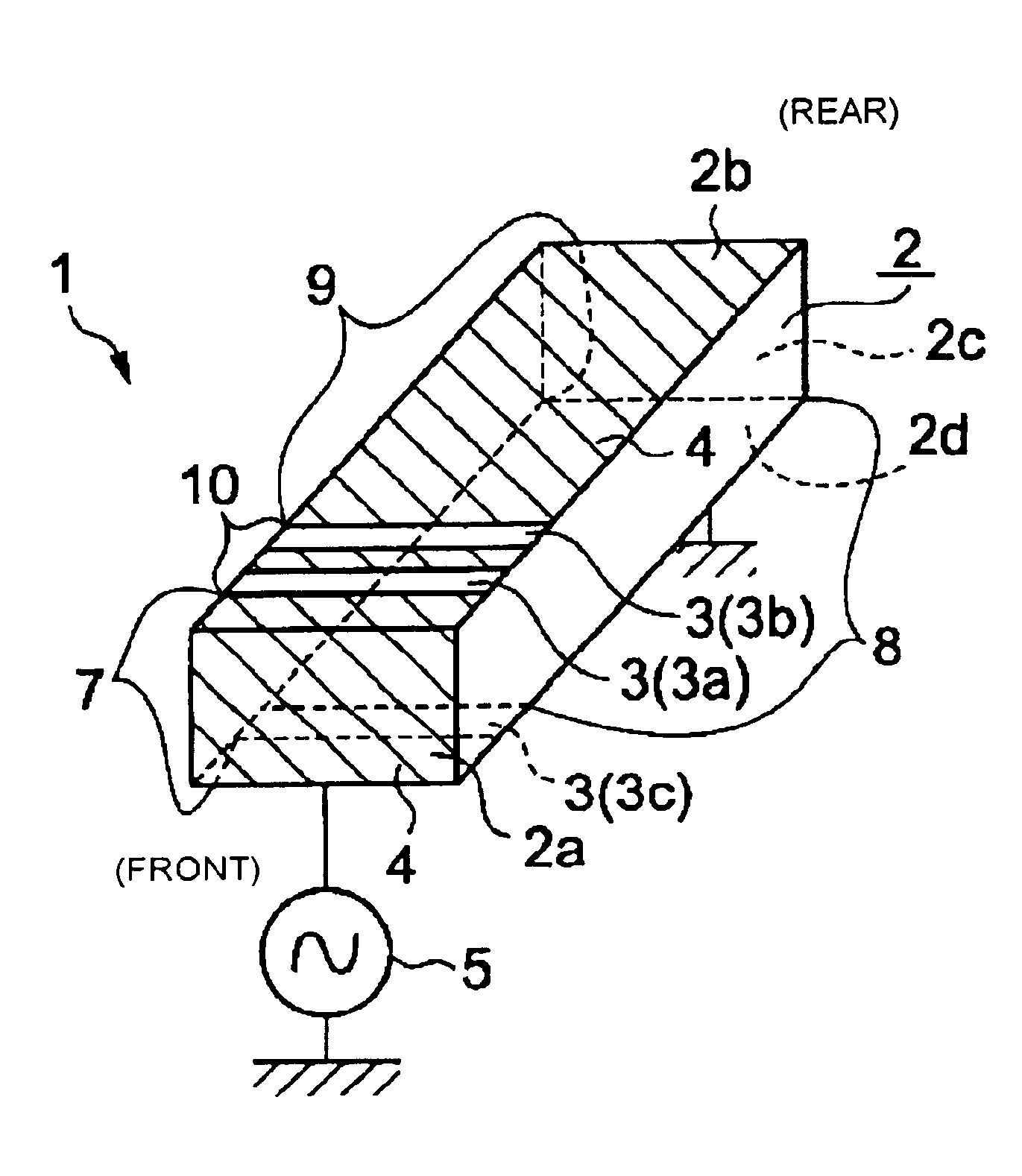
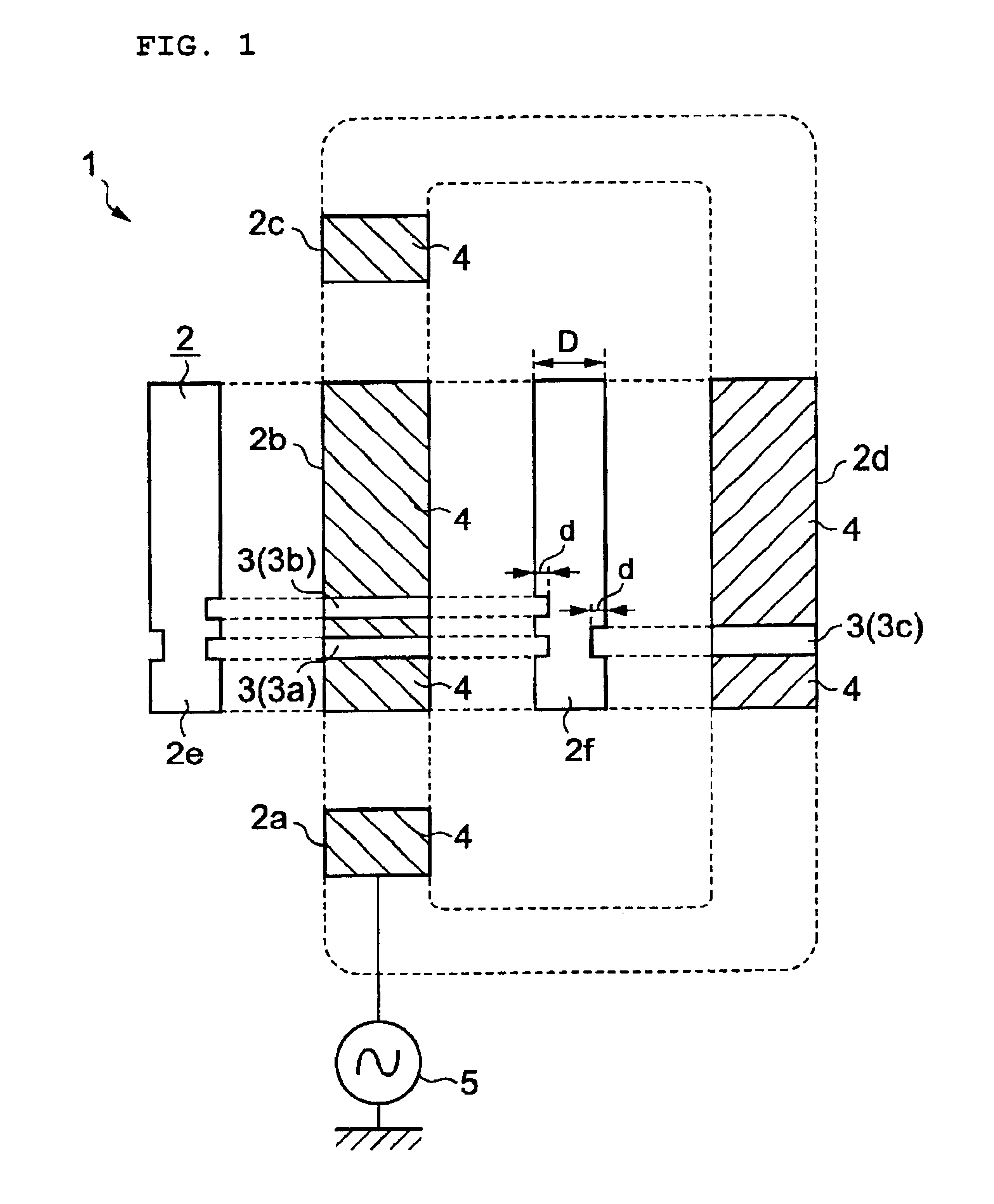
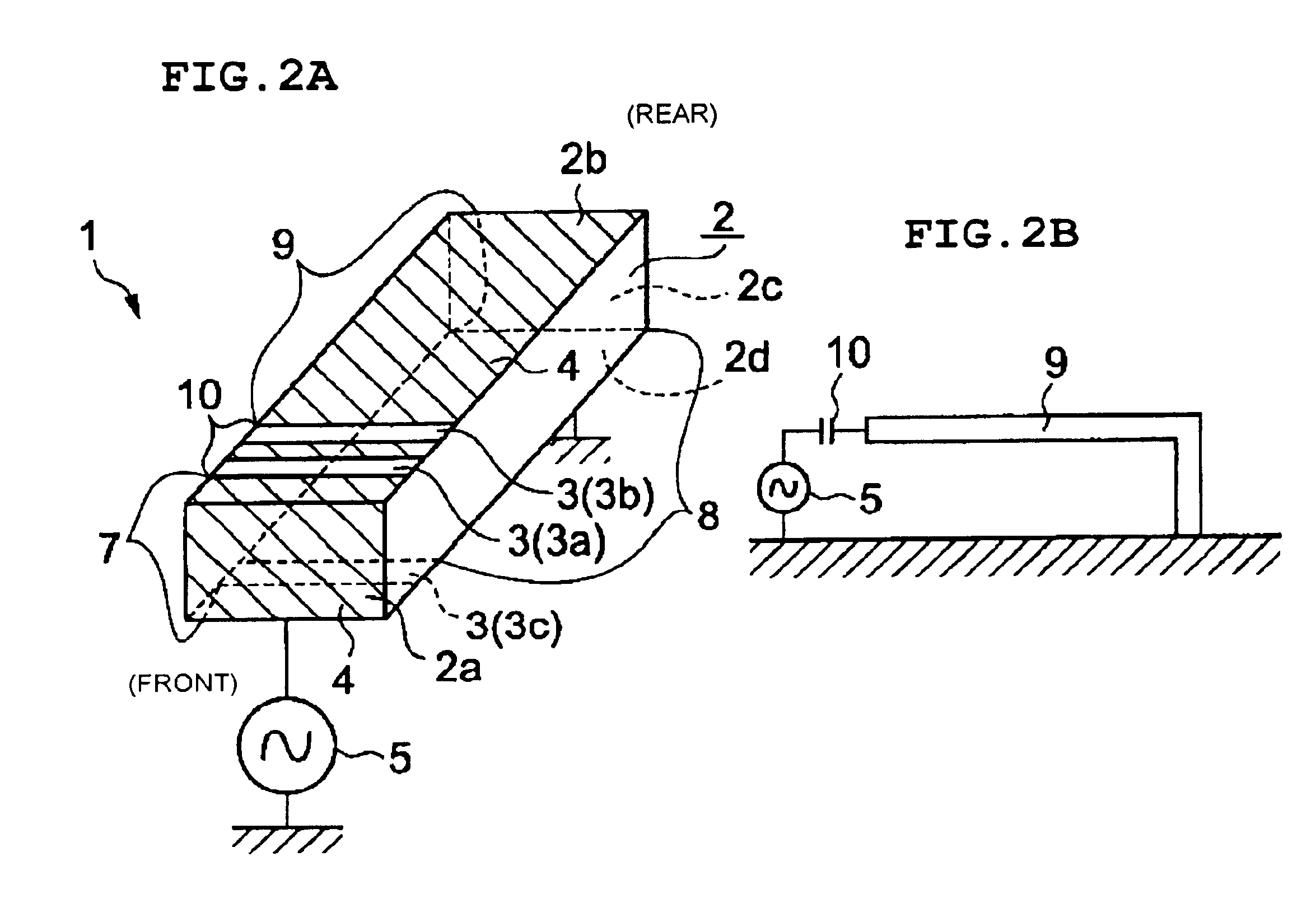
[0058]FIG. 1 is a development view of a surface mount antenna 1 according to a first preferred embodiment of the present invention. FIG. 2A is a schematic perspective view of this surface mount antenna 1 including a substantially rectangular dielectric substrate 2. This dielectric substrate 2 has four continuous surfaces, that is, a front end surface 2a, a top surface 2b, a rear end surface 2c, and a bottom surface 2d, and a conductive film 4 that is disposed on these surfaces and that is separated into a plurality of conductive film parts by a plurality of slits 3a, 3b, and 3c.
[0059]These slits 3a, 3b, and 3c extend over the width of the dielectric substrate 2 in a direction crossing the direction in which the front end surface 2a, the top surface 2b, the rear end surface 2c, and the bottom surface 2d surround the substrate 2 in this order. In this preferred embodimen...
PUM
| Property | Measurement | Unit |
|---|---|---|
| Thickness | aaaaa | aaaaa |
| Width | aaaaa | aaaaa |
| Depth | aaaaa | aaaaa |
Abstract
Description
Claims
Application Information