Current sensor

a current sensor and sensor technology, applied in the field of current sensors, can solve the problems of complicated and long procedures, and require lots of guesswork

Inactive Publication Date: 2005-05-10
KVH IND INC
View PDF107 Cites 19 Cited by
  • Summary
  • Abstract
  • Description
  • Claims
  • Application Information

AI Technical Summary

Benefits of technology

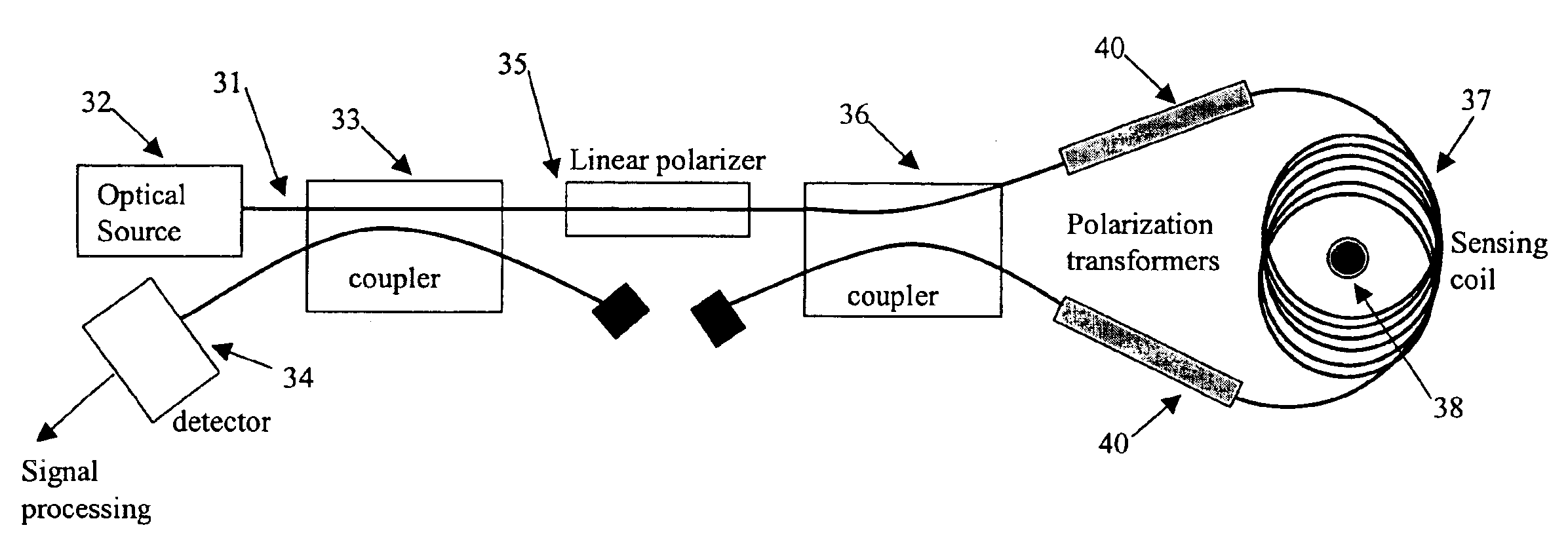
[0007]A current sensor is presented including a source of linearly polarized light; two transformers of polarized light as in claim 1 for transforming the linearly polarized light to circularly polarized light; a coil of optical fiber having one or more turns; a directional coupler for optically coupling the linearly polarized light to the transformers; an optical detector for receiving the light beams which have traversed the coil for producing an output signal indicative of a magnetic field produced by an electric current, and a second directional coupler for coupling the light beams to the detector.
[0008]A current sensor is presented including a source of linearly polarized light; two transformers of polarized light as described above for transforming the linearly polarized light to circularly polarized light; a coil of optical fiber having one or more turns; a directional coupler for optically coupling the linearly polarized light to the transformers; and an optical detector for receiving the light beams which have traversed the coil for producing an output signal indicative of a magnetic field produced by an electric current, which detector is deployed at a rear facet of the source.
[0009]A current sensor is presented including a source of linearly polarized light, a transformer of polarized light as described above for transforming the linearly polarized light to circularly polarized light, a coil of optical fiber having one or more turns, a reflector for reflecting the beam which has traversed the coil, and an optical detector for receiving the light beam which has traversed the coil twice for producing an output signal indicative of a magnetic field produced by an electric current.
[0010]A method of detecting the current in a conductor is also presented including generating a linearly polarized light beam, dividing the beam in a directional coupler into two beams, transforming the two beams into circularly polarized light beams using polarization transformers as described above, coupling the two circularly polarized beams into opposite ends of a coil of optical fiber having one or more turns, which coil is disposed around a conductor of electrical current, permitting the beam to pass through the coil in opposite directions, transforming the circularly polarized beams back into linearly polarized beams by means of the polarization transformers, combining the two beams into a combined beam by means of the directional coupler, passing the combined beam through a linear polarizer, and receiving said combined beam with an optical detector for producing an output signal indicative of a magnetic field produced by the electric current in the conductor.
[0011]A method of detecting the current in a conductor is also presented including generating a linearly polarized light beam, transforming the linearly polarized light beam into circularly polarized light beams, using a polarization transformer as described above, the transformer arrayed so that the beam emerging contains a component polarized in a clockwise direction and a component polarized in a counterclockwise direction, coupling the beam into an end of a coil of optical fiber having one or more turns, which coil is disposed around a conductor of electrical current, permitting the beam to pass through the coil, reflecting the beam at the end of the coil so that it passes through the coil a second time in the opposite direction, transforming the beam back into a linearly polarized beam by means of the polarization transformer, passing the beam through a linear polarizer, and receiving said beam with an optical detector for producing an output signal indicative of a magnetic field produced by the electric current in the conductor.

Problems solved by technology

Needless to say, this is a tedious and lengthy procedure requiring lots of guesswork.

Method used


Image

  • Current sensor
  • Current sensor
  • Current sensor

Examples


Embodiment Construction

)

[0016]It is often desirable to transform the polarization of a beam of light from one state to another. For this purpose optical devices have been fabricated that input linearly polarized light and output elliptically polarized light. These devices typically function by causing one of two incident linearly polarized light beams to lag behind the other by a pre-selected phase difference. Altering the relative phase of the two incident beams has the effect of changing the state of polarization of the light that exits the optical device. Before considering how these devices of the prior art perform the transformation of linearly to elliptically polarized light and before presenting the detailed description of the preferred embodiment of the present invention, it will be useful to first recall how elliptically polarized light arises.

[0017]Two orthogonal electric fields, Ex and Ey, both propagating in the z direction can be described by the following two equations

Ex=i E0x cos(kz−ωt)  (1...


PUM


Abstract

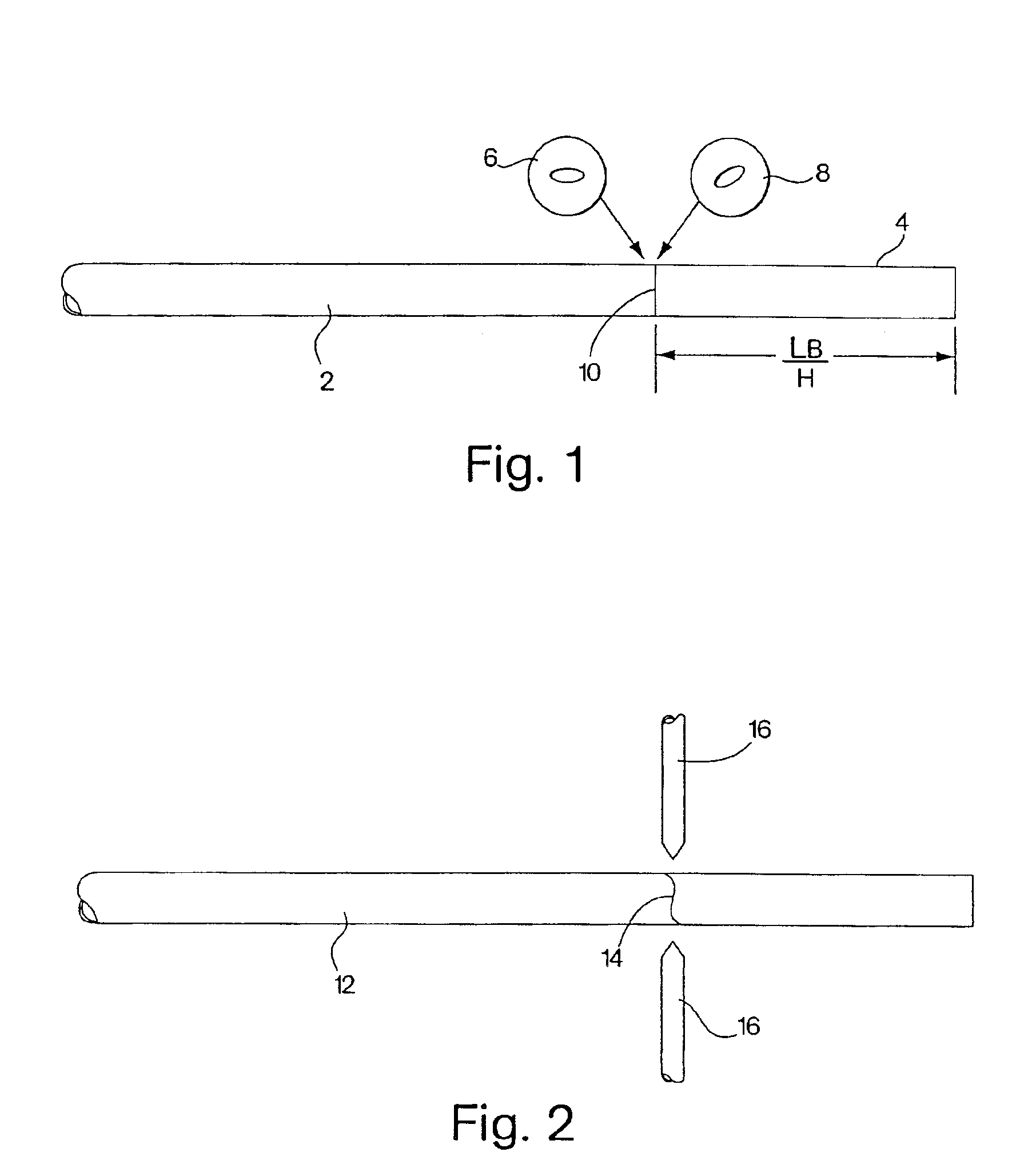
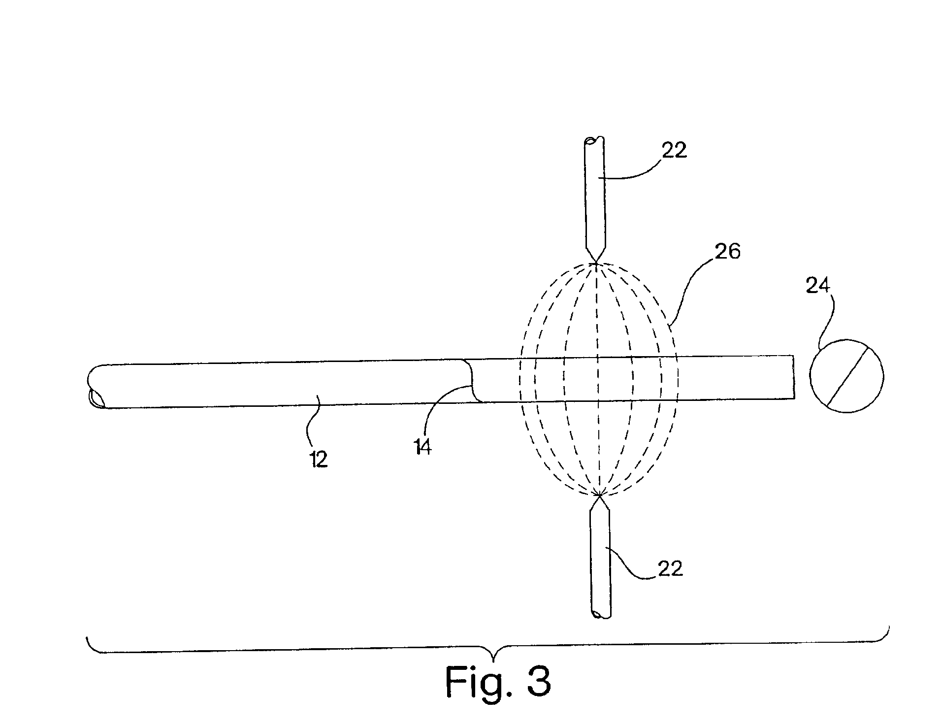
A method and device for measuring the current in a conductor are presented. They utilize the Faraday effect on counter-propagating circularly polarized beams of light in a fiber optic coil. The light beams are transformed to and from circular polarization by a polarization transformer comprised of a birefringent fiber with a twist through an appropriate angle at an appropriate distance from one end.

Description

CROSS-REFERENCE TO RELATED APPLICATIONS[0001]This application is a continuation-in-part of U.S. patent application Ser. No. 09 / 337,231 filed on Jun. 22, 1999. This application is also based upon and claims priority to the following U.S. patent applications. U.S. provisional patent application, Ser. application No. 60 / 119,999, filed on Feb. 11, 1999; U.S. provisional patent application, Ser. application No. 60 / 120,000, filed on Feb. 11, 1999; U.S. provisional patent application, Ser. application No. 60 / 133,357, filed on May 10, 1999; and U.S. provisional patent application, Ser. application No. 60 / 134,154, filed on May 14, 1999. This application is also based upon U.S. application Ser. No. 09 / 337,223, invented by Richard Dyott, which was filed concurrently with U.S. patent application Ser. No. 09 / 337,231 on Jun. 22, 1999. All of the aforementioned applications are hereby incorporated by reference.BACKGROUND OF THE INVENTION[0002]1. Field of the Invention[0003]This application relates...

Claims


Application Information

Patent Timeline
Patent Type & Authority Patents(United States)
IPC IPC(8): G02B6/10H01S5/06H01S5/065H01S5/00H01S5/062G01R15/24
CPCG01R15/246G02B6/105H01S5/0607H01S5/065H01S5/06209H01S5/0652H01S5/06233
Inventor DYOTT, RICHARD B.
Owner KVH IND INC
Why Eureka
Try Eureka