Reciprocating cutting tools having devices for limiting scattering of cutting chips

a technology of cutting tools and scattering devices, which is applied in the direction of manufacturing tools, portable power-driven tools, metal sawing accessories, etc., can solve the problem that the cost of manufacturing is not significantly increased to provide both functions, and achieve the effect of convenient and reliable operation

Inactive Publication Date: 2005-05-17
MAKITA CORP
View PDF16 Cites 43 Cited by
  • Summary
  • Abstract
  • Description
  • Claims
  • Application Information

AI Technical Summary

Benefits of technology

[0006]Therefore, one object of the present teachings is to provide improved reciprocating cutting tools that can be operated more easily and reliably.

Problems solved by technology

Further, the cut chips (that may stick to the transparent cover in the known tool) will not prevent the operator from observing the cut portion of the workpiece.
Therefore, manufacturing costs are not significantly increased to provide both functions.

Method used


Image

  • Reciprocating cutting tools having devices for limiting scattering of cutting chips
  • Reciprocating cutting tools having devices for limiting scattering of cutting chips
  • Reciprocating cutting tools having devices for limiting scattering of cutting chips

Examples


Embodiment Construction

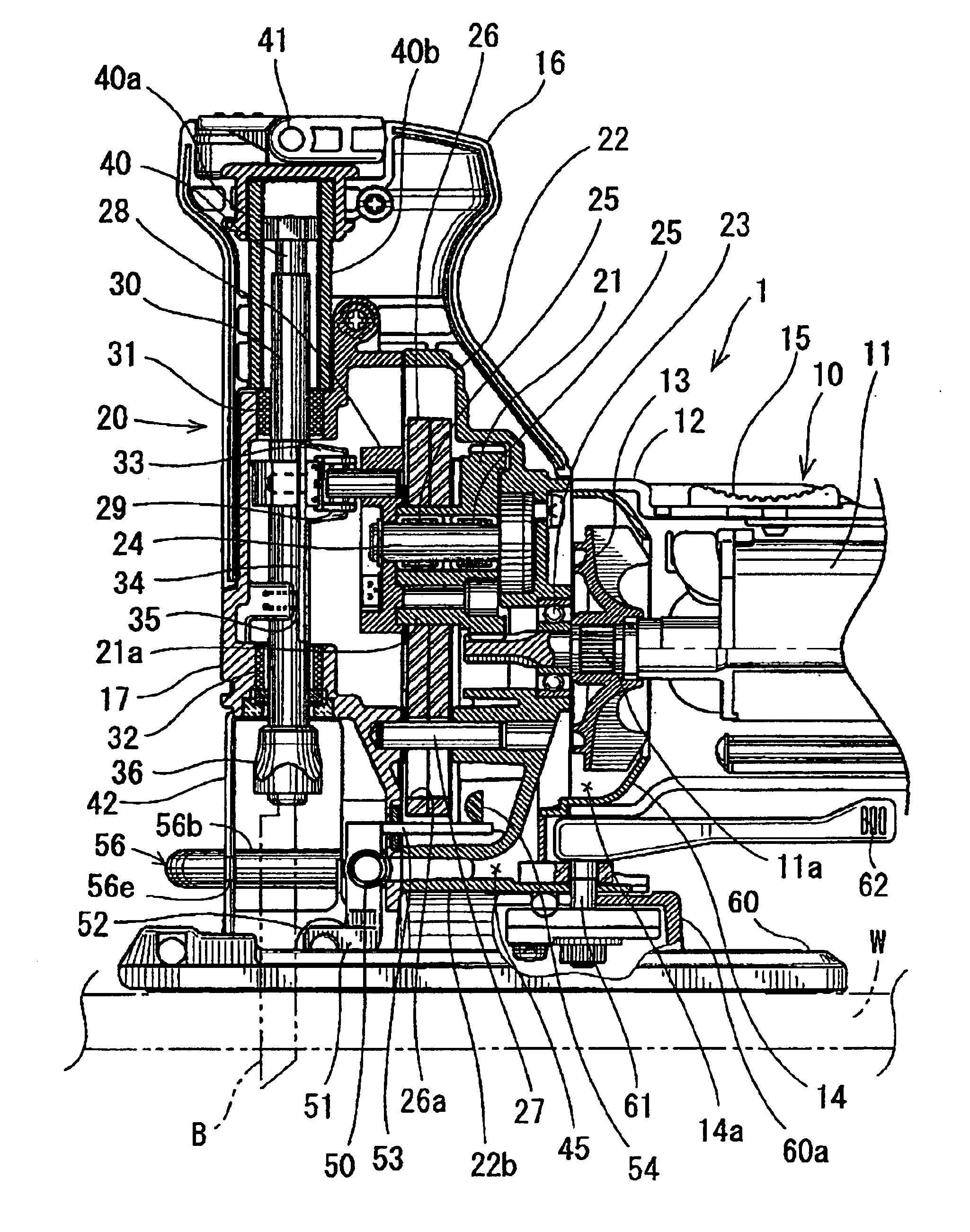
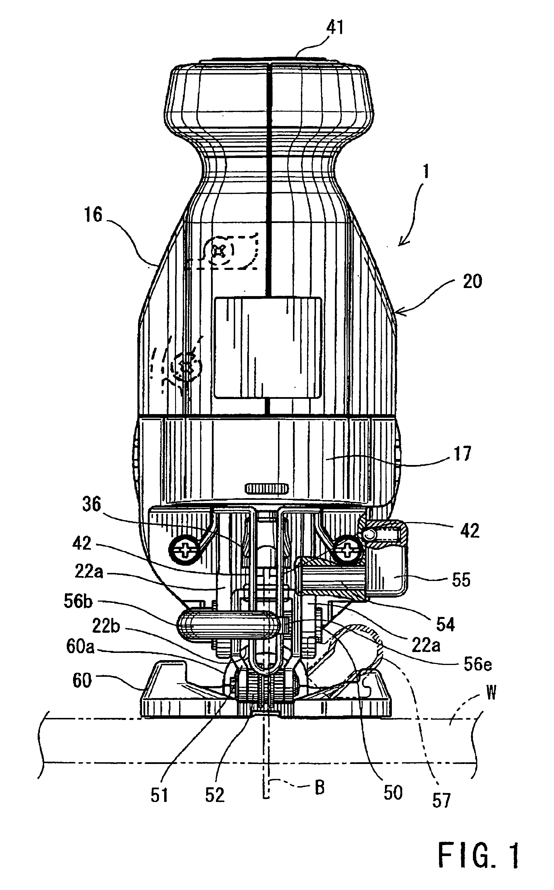
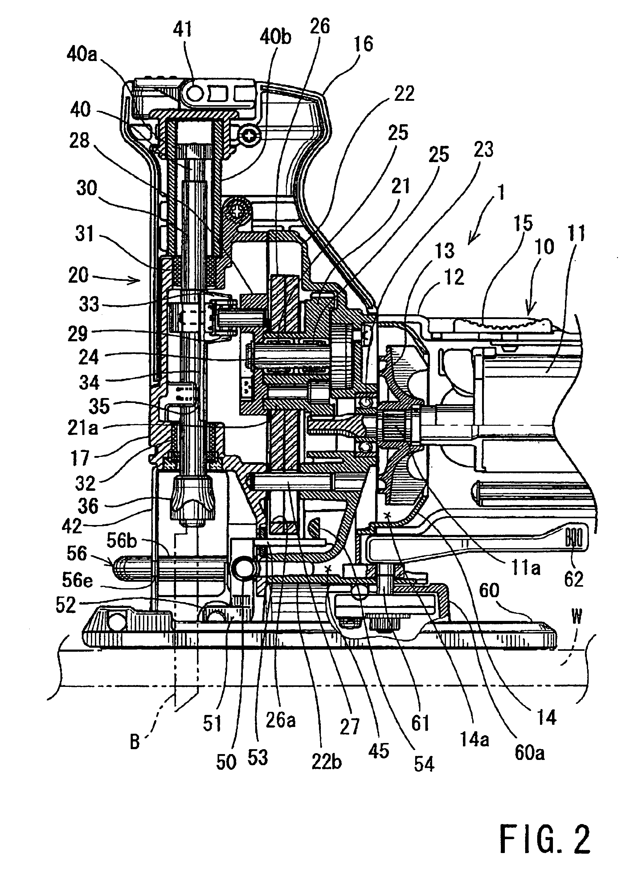
[0032]In another embodiment of the present teachings, reciprocating cutting tools may include a motor that serves as a drive source. A drive mechanism may convert the rotation of the motor into reciprocating movement of a blade, so that the reciprocating blade may cut a workpiece. The motor may also drive a fan or blower in order to produce an air stream for cooling the motor. An air channel may be defined to guide the air stream, so that the air stream may be blown out or exhausted toward or adjacent to the blade or a portion of a workpiece that will be cut by the blade. Cutting chips produced at the cut portion may be drawn into a chip collection nozzle, which nozzle may be connected to a chip collecting device.

[0033]Because the air stream, i.e. the cooling air, may limit the extent that the cutting chips will scatter, the operator can observe the cut portion of the workpiece through the air stream without interference by the cutting chips. Thus, the problems of known devices that...


PUM

PropertyMeasurementUnit
angleaaaaaaaaaa
angleaaaaaaaaaa
suctionaaaaaaaaaa

Abstract

Reciprocating cutting tools (1, 90, 100) may include a drive source (11) for reciprocally driving a blade (B). The drive source may also drive a blower (13) in order to generate an air stream. An air channel (50, 56, 50, 70, 85, 80) may guide the air stream to a position adjacent to the blade or a workpiece (W) that will be cut by the blade. Further, a chip collector nozzle (57) may draw or suction cutting chips away from the workpiece that has been cut by the blade.

Description

BACKGROUND OF THE INVENTION[0001]1. Field of the Invention[0002]The present invention relates to reciprocating cutting tools, such as jigsaws, which reciprocally move a blade in order to cut a workpiece. More particularly, the present invention relates to reciprocating cutting tools having devices for limiting cutting chips that may be produced during a cutting operation from scattering. The present invention also relates to methods for limiting the scattering extent of the cutting chips.[0003]2. Description of the Related Art[0004]Japanese Laid-open Utility Model Publication No. 6-75705 discloses a jigsaw that has a substantially U-shaped cover. The cover surrounds the front, right and left sides of a blade in order to prevent cut pieces and cutting chips from scattering to the surrounding area. According to this arrangement, the cover contains the cut chips and prevents the cut chips from scattering outside of the cover. Further, a chip collection nozzle is attached to the cover i...

Claims


Application Information

Patent Timeline
Patent Type & Authority Patents(United States)
IPC IPC(8): B23D59/00B23Q11/00B23D51/00B23D49/14B27B19/00B27G3/00
CPCB23D59/006B23Q11/006B23Q11/005
Inventor OKUMURA, MICHIOTAKAHASHI, YUJIKONDO, MASAKIITO, HIDENORIHIRABAYASHI, SHINJI
Owner MAKITA CORP
Why Eureka
Try Eureka