Joystick

a joystick and z-axis technology, applied in the field of joysticks, can solve the problems of difficult design of joysticks, shortening the useful life of many existing joysticks, and affecting the use of joysticks, etc., and achieve the effect of reliable, durable and comfortabl

Inactive Publication Date: 2005-05-17
PELCO INC
View PDF29 Cites 51 Cited by
  • Summary
  • Abstract
  • Description
  • Claims
  • Application Information

AI Technical Summary

Benefits of technology

[0013]The improved joystick of the present invention provides a durable, reliable and comfortable joystick for use in precision applications such as controlling a surveillance camera. The joystick of the present invention incorporates mechanical linkages that convert the user's motion into the rotation of three different resistive potentiometers, one for each of 3 axes of movement (X, Y and Z). The linkages for two of these axes (X and Y) are incorporated into the joystick base, and the linkage for the remaining axis (Z) is uniquely incorporated into the joystick handle.
[0014]The mechanical linkage of the two lower axes has been designed to provide high strength and long life. The primary load carrying members of the two lower axes are manufactured from high strength metal. This allows the joystick to endure much higher twisting forces than previous joystick designs have allowed. The surfaces that are exposed to rotation and wear are preferably made of self-lubricating materials for a non-greasy feel, but may have lubrication added if desired.

Problems solved by technology

Unexpected movements by the subject being tracked, or a need by the operator to suddenly change the direction of the camera may often result in harsh treatment of the joystick used to control the camera.
The useful lives of many existing joysticks are often cut short by such normal operator use (and / or abuse) because the joystick devices are flimsy, poorly constructed, or poorly designed and subject to breakage in a relatively short period of time.
Converting motion imparted along the Z-axis of a joystick has been a particularly troublesome obstacle to joystick design.
This is because many existing joysticks cannot withstand excess rotational twisting or turning motion imparted around the Z-axis.
However, even minor over-twisting of a joystick can lead to wrapping and ultimately disconnection of wires leading to the joystick, as well as destruction of, or disconnection of the joystick from the mechanism of cross axes in the joystick base which receive the motion imparted to the joystick by the user.
Either situation is unacceptable in that it renders the joystick inoperable.
However, there is nothing in this device to prevent unchecked rotation of the joystick handle, and very few contacts are provided on the switch such that considerable rotation around the Z-axis will not be detected at all.
Moreover, the contacts themselves do not yield the more precise rotational detection information that can be provided by a potentiometer.
Many such tension springs suffer from the drawbacks of being easily disconnected from their supports, and from wearing out after constant use.
However, after the adjustments have been made, over time the adjustable mounting structures tend to become loose, thereby affecting the signals generated by the potentiometers, and skewing the control of the joystick.
Such lubricants may cause problems in that they may spread onto the joystick itself making it greasy, repulsive and difficult to control.

Method used


Image

  • Joystick
  • Joystick
  • Joystick

Examples


Embodiment Construction

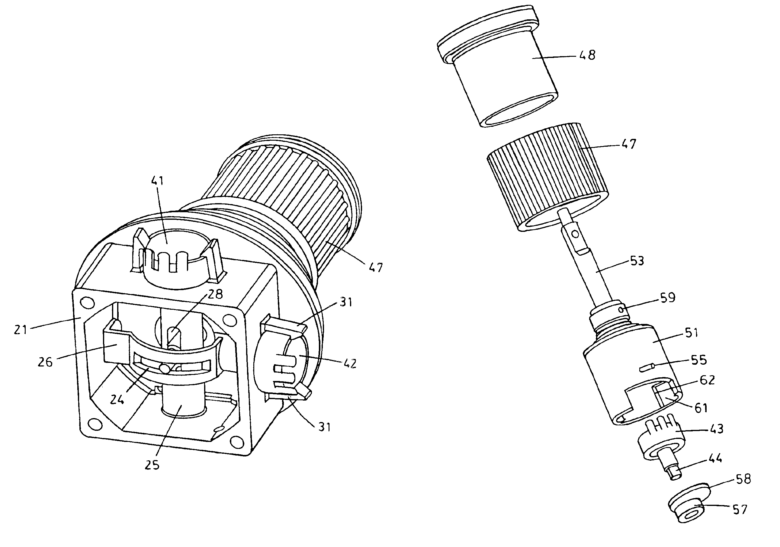
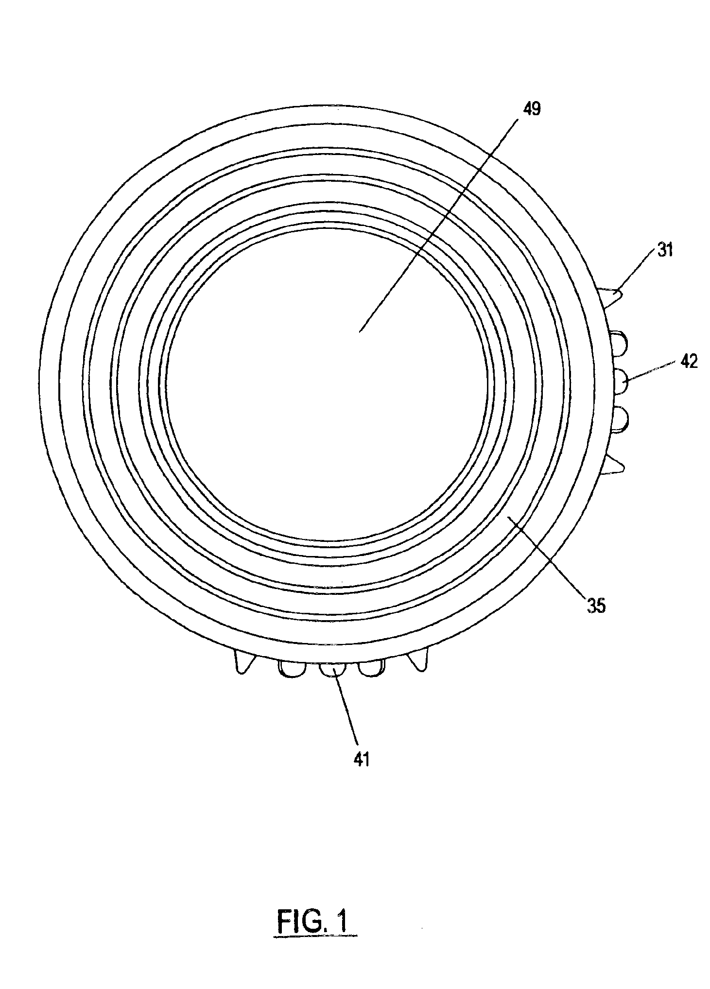
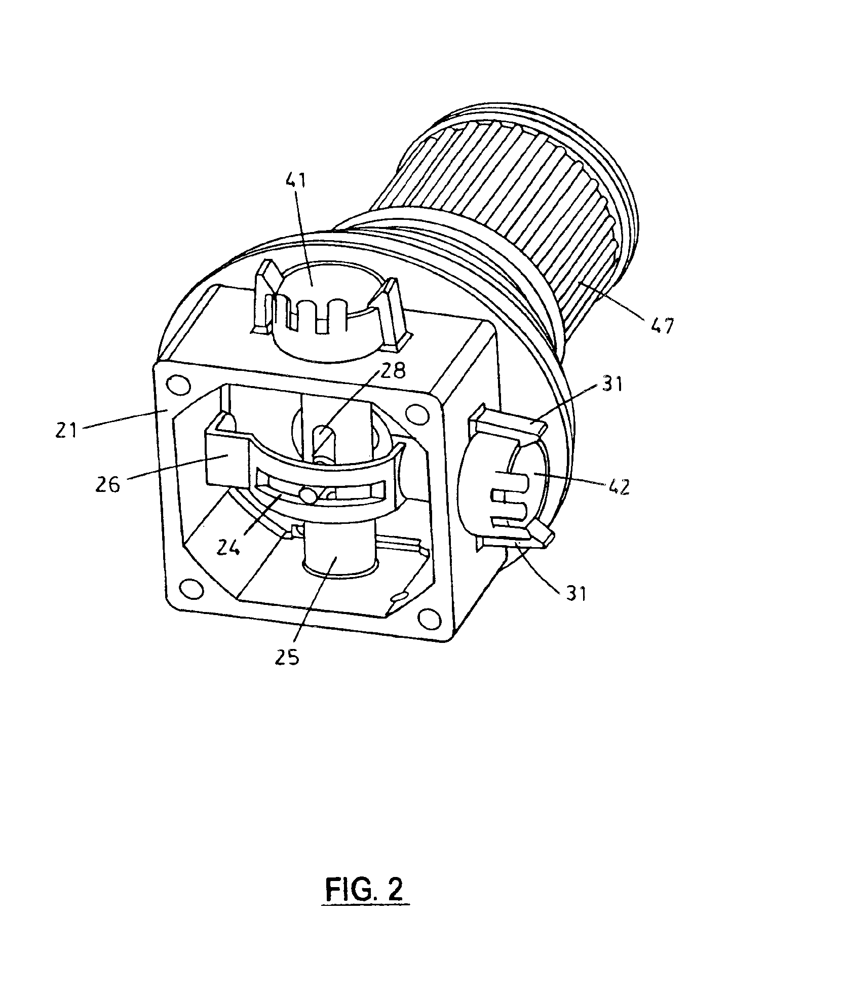
[0044]Referring to the drawings wherein like reference characters designate like or corresponding parts throughout the several views, and referring particularly to FIGS. 2, 3 and 8, it is seen that the base assembly of the present invention includes a square or rectangular base member 21 made of self-lubricating plastic or other low friction material. A pair of openings 22, 23 on opposite sides of base 21 are provided for receiving a rotatable rod or axle 25. A bearing 27 made of self-lubricating material is provided for holding rod 25 in opening 23, and a snap ring 29 is used to hold rod 25 in opening 22. Rod 25 includes an elongated central slotted opening 28 for receiving the shaft 53 of the joystick handle. Deflection of shaft 53 causes rod 25 to rotate. One end of rod 25 is engaged with a first potentiometer 41 that is snap fit into place over opening 23 using tabs 31. Thus, rotational movement of rod 25 caused by movement of the joystick shaft 53 along the X-axis will be impar...


PUM


Abstract

A durable, reliable and comfortable joystick for use in precision applications such as controlling a surveillance camera. The joystick of the present invention incorporates mechanical linkages that convert the user's motion into the rotation of three different resistive potentiometers, one for each of 3 axes of movement (X, Y and Z). The potentiometers and linkages for the X- and Y-axes are incorporated into the joystick base, and the potentiometer and linkage for the Z-axis is uniquely incorporated into the joystick handle. Rotation of the handle is restricted in order to prevent damage to the internal parts and preserve the life of the joystick.

Description

[0001]This application claims the benefit of U.S. Provisional Application No. 60 / 308,648 filed Jul. 27, 2001,BACKGROUND OF THE INVENTION[0002]1. Field of the Invention[0003]The present invention relates to apparatus control, and more particularly to an improved joystick for use in controlling the movement of an apparatus such as a surveillance camera that is extremely durable and that is capable of withstanding considerable operator abuse, while providing comfortable and precise control.[0004]2. Description of the Prior Art[0005]Mouse devices and joystick type controllers are well-known coordinate input devices for computer systems. Joystick devices generally include a rectangularly shaped base from which the joystick shaft protrudes. The shaft may be shifted in an inclined manner in any direction, and an angle detection mechanism is provided in the base to detect the inclined angle and direction along the X and Y axes. The detected angle and direction are then supplied to a compute...

Claims


Application Information

Patent Timeline
Patent Type & Authority Patents(United States)
IPC IPC(8): G05G9/047G05G9/00
CPCG05G9/047G05G9/04792G05G9/04796Y10T74/20201G05G2009/04777G05G2009/04781G05G2009/04748
Inventor TEWS, ERIK
Owner PELCO INC
Why Eureka
Try Eureka