Cutting element having a substrate, a transition layer and an ultra hard material layer

a cutting element and transition layer technology, applied in earth drilling and mining, manufacturing tools, construction, etc., can solve the problems of laborious methods currently used for forming cutting elements with non-uniform interfaces between cutting layers and substrates, between cutting layers and transition layers, and between substrates and transition layers

Inactive Publication Date: 2005-05-17
SMITH INT INC
View PDF18 Cites 133 Cited by
  • Summary
  • Abstract
  • Description
  • Claims
  • Application Information

AI Technical Summary

Benefits of technology

[0011]To form a non-uniform interface between an ultra hard material cutting layer and a substrate, for example, a sheet of material which after the sintering process is the same as the substrate, is embossed on one face for forming the desired non-uniform interface. For illustrative purposes this sheet is referred to herein as the “substrate material sheet.” The substrate material sheet is cut and placed on an end of the substrate. A second sheet ultra hard material is formed and is embossed for forming a non-uniform face complementary to the embossed non-uniform face on the substrate layer. The sheet is cut and the two sheets are mated with each other over the substrate. The entire assembly consisting of the substrate, substrate material sheet and ultra hard material sheet are then sintered together, causing the substrate material sheet to become integral with the substrate, and the ultra hard material sheet to bond to the resulting substrate for forming a non-uniform interface between the resulting substrate and the ultra hard material.

Problems solved by technology

When transition layers are incorporated, one or both faces of the transition layers may also be non-uniform.
As can be seen, the methods currently used for forming a cutting element having non-uniform interfaces between the cutting layer and the substrate, or between the cutting layer and a transition layer, or between the substrate and a transition layer may be labor intensive.

Method used


Image

  • Cutting element having a substrate, a transition layer and an ultra hard material layer
  • Cutting element having a substrate, a transition layer and an ultra hard material layer
  • Cutting element having a substrate, a transition layer and an ultra hard material layer

Examples


Embodiment Construction

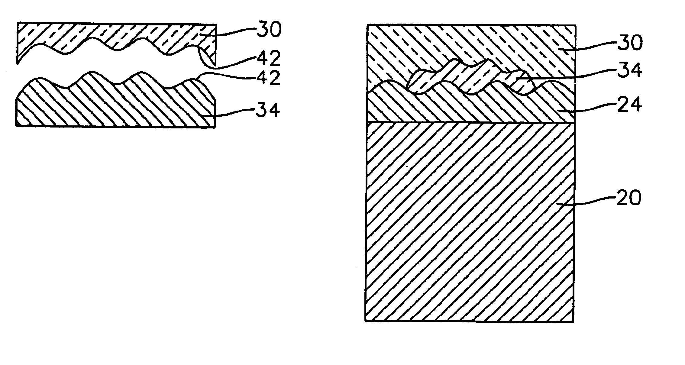
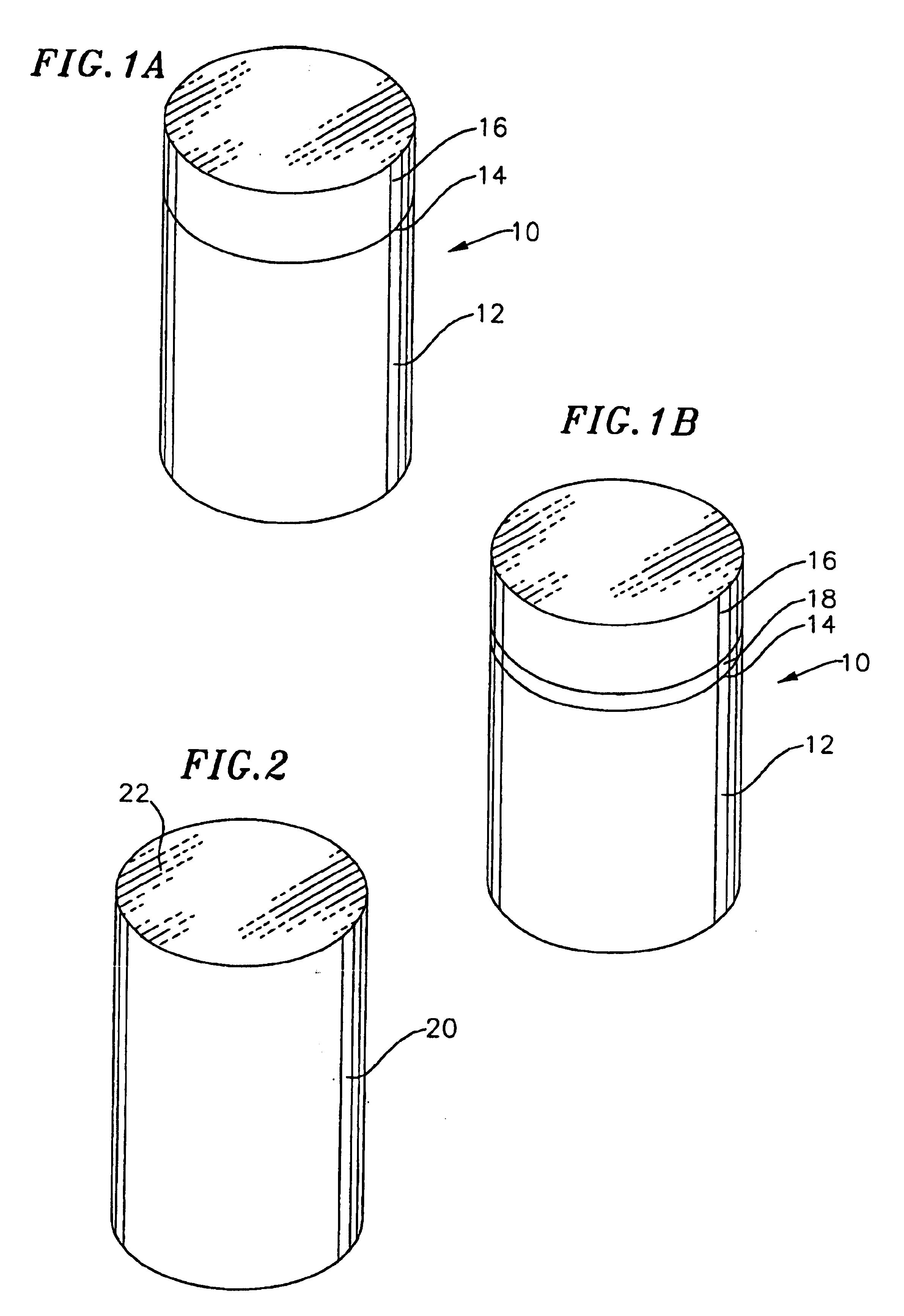
[0029]For illustrative purposes, this invention will be described in terms of a rock bit shear cutter 10 having a cylindrical body 12 (FIG. 1A). However, as it will be apparent to one skilled in the art, the present invention can be used to form other types of cutting elements. The body 12 of a shear cutter is typically made from cemented tungsten carbide. An end face of the body forms a cutting face 14. An ultra hard material layer 16 such as PCD or PCBN is bonded on the cutting face forming a cutting layer or cutting face. A transition layer 18 or multiple transition layers having properties which preferably are intermediate between the substrate and the cutting layer may also be incorporated between the cutting face and the cutting layer (FIG. 1B). A transition layer may for example be a layer of tungsten carbide, PCD or PCBN having varying particle grain sizes or may be formed from a combination these materials.

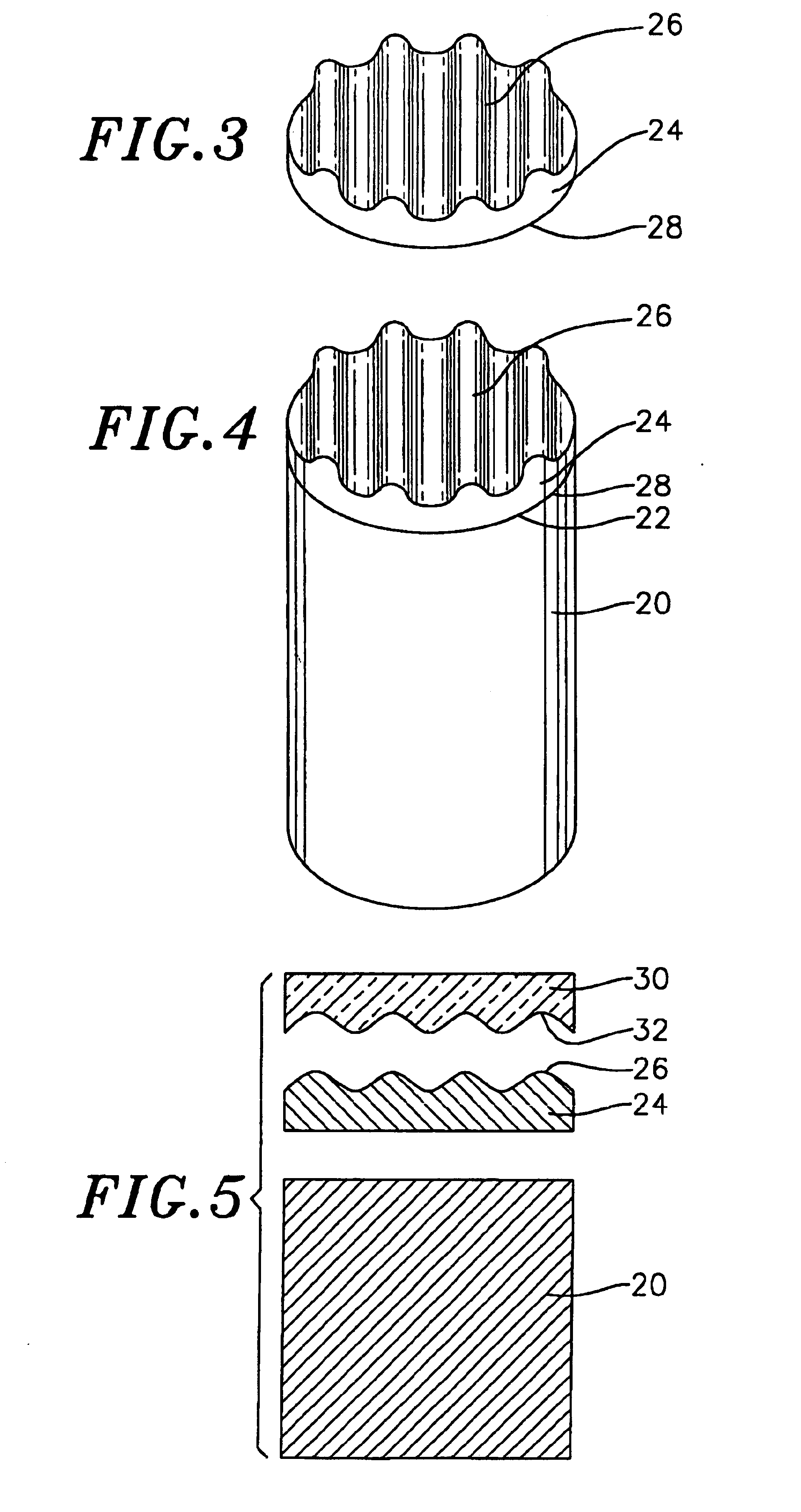
[0030]In a first embodiment, a presintered substrate 20 having an en...


PUM

PropertyMeasurementUnit
thicknessaaaaaaaaaa
thicknessaaaaaaaaaa
ultra hardaaaaaaaaaa

Abstract

A non-uniform interface is formed between a polycrystalline ultra hard material layer and a cemented tungsten carbide substrate, or a polycrystalline ultra hard material layer and a transition layer, or a transition layer and a substrate of a cutting element. A first sheet made from an intermediate material is formed and embossed on one face forming a non-uniform pattern raised in relief on the face. The embossed sheet is placed on a face of a presintered substrate. An ultra hard material sheet is formed and embossed, forming a non-uniform face complementary to the non-uniform face on the sheet of intermediate material. The ultra hard material sheet is placed over the intermediate material sheet so that the complementary faces are adjacent to each other. The assembly of substrate and sheets is sintered in a HPHT process. The sintering process causes the first sheet to become integral with the substrate and results in a substrate having a non-uniform cutting face onto which is bonded a polycrystalline ultra hard material layer. Embossed transition material sheets may be employed between the ultra hard material sheet and the first sheet to form transition layers with uniform or non-uniform interfaces.

Description

[0001]This application is a divisional of patent application Ser. No. 09 / 047,801 filed on Mar. 25, 1998 and issued as U.S. Pat. No. 6,193,001.BACKGROUND OF THE INVENTION[0002]This invention relates to a method for forming cutting elements and specifically to a method for forming cutting elements having a non-uniform interface adjacent their cutting layers.[0003]Cutting elements, such as shear cutters for rock bits, for example, typically have a body (or substrate) which has a cutting face. A cutting layer (sometimes referred to as a “cutting table”) is bonded to the cutting face of the body. The body is generally made from cemented tungsten carbide (sometimes referred to simply as “tungsten carbide” or “carbide”), while the cutting layer is made from a polycrystalline ultra hard material, such as polycrystalline diamond (“PCD”) or polycrystalline cubic boron nitride (“PCBN”). Moreover, these cutters may employ transition layers bonded between the substrate and the cutting layer. The...

Claims


Application Information

Patent Timeline
Patent Type & Authority Patents(United States)
IPC IPC(8): E21B10/46E21B10/56E21B10/573
CPCE21B10/5735Y10S76/11Y10S76/12
Inventor EYRE, RONALD K.KESHAVAN, MADAPUSI K.
Owner SMITH INT INC
Why Eureka
Try Eureka