Aircraft with forward opening inlay spoilers for yaw control

a technology of spoiler and aircraft, applied in the field of aircraft control, can solve problems such as drag on one wing or the other

Inactive Publication Date: 2005-05-17
NORTHROP GRUMMAN SYST CORP
View PDF49 Cites 20 Cited by
  • Summary
  • Abstract
  • Description
  • Claims
  • Application Information

AI Technical Summary

Benefits of technology

[0010]The forward opening control surfaces produce drag and a sid...

Problems solved by technology

The opening of these forward opening sur...

Method used


Image

  • Aircraft with forward opening inlay spoilers for yaw control
  • Aircraft with forward opening inlay spoilers for yaw control
  • Aircraft with forward opening inlay spoilers for yaw control

Examples


Embodiment Construction

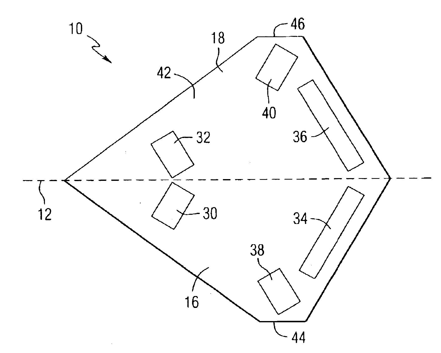
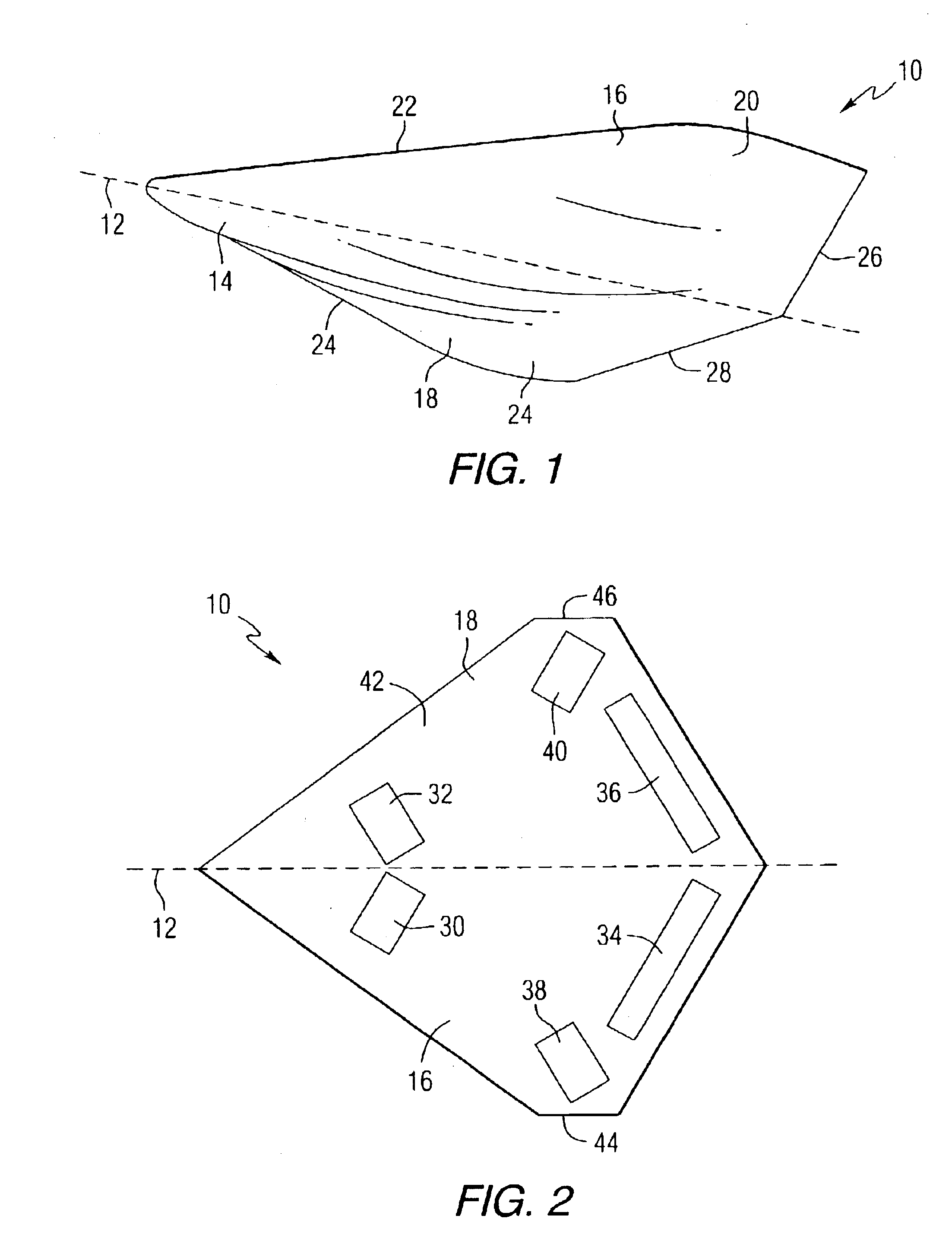
[0019]In accordance with an aspect of the invention, a flying wing tailless aircraft comprises an integrated fuselage / wing that generally defines the aircraft and control surfaces integrally formed therewith. FIG. 1 is a schematic representation of a perspective view of a swept back aircraft 10 that can be constructed in accordance with this invention. The aircraft 10 has a longitudinal axis 12 and is provided with a central fuselage 14 positioned along the longitudinal axis. A pair of opposing swept back wings 16, 18 extend laterally and in an aftward direction from the fuselage 14. The wings 16, 18 have an outer contour which blends smoothly and continuously with that of the fuselage 14. In this respect, the fuselage 14 is completely integrated with the wings 16, 18. This smooth integration is contemplated to give the entire aircraft 10 the appearance and functionality of being a single wing. Thus, the integrated fuselage / wing configuration generally defines the aircraft 10. As su...


PUM


Abstract

An aircraft comprises first and second wings positioned on opposite sides of a longitudinal axis, a first forward opening control surface attached to an upper surface of the first wing, and a second forward opening control surface attached to an upper surface of the second wing, wherein each of the first and second hinges is canted with respect to a direction perpendicular to a longitudinal axis of the aircraft. A method of providing yaw control of an aircraft is also provided. The method comprises the steps of providing a first forward opening, canted spoiler in a top surface of a first wing of the aircraft, providing a second forward opening, canted spoiler in a top surface of a second wing of the aircraft, and operating the first and second spoilers differentially to create a yaw moment. The creation of yaw moments without any down force has application in sweptback wings where the tips are behind the center of gravity of the aircraft. The advantage is in reducing radar cross section over traditional (forward hinged, rearward opening) spoilers where there must be a spoiler on the bottom side to counter the down force created by the top spoiler.

Description

FIELD OF THE INVENTION[0001]The invention relates generally to aircraft, and more specifically, to systems and methods for control of an aircraft.BACKGROUND INFORMATION[0002]Aircraft purposefully built to avoid radar detection are characterized by shapes with as few different angles as possible. This results in edges which are parallel to each other even if on opposite sides of the aircraft. It is also desirable to have a fuselage that is blended into the wing where any shapes of small radius can be placed on the upper side, unseen by ground radar. Because of this smooth integration, these aircraft are sometimes referred as “flying wings.” An example of a flying wing aircraft is the B-2 bomber. An aircraft of low radar cross section is devoid of any unnecessary protuberances such as a vertical stabilizer, having its function replaced by control surfaces that increase the drag on one wing or the other only when needed and otherwise lie against the wing to become part of the wing.[000...

Claims


Application Information

Patent Timeline
IPC IPC(8): B64C9/00B64C39/10B64C1/00B64C5/08B64D7/00B64C5/00B64C39/00B64C9/32
CPCB64C1/0009B64C5/08B64C9/32B64C9/323B64C39/10B64D7/00Y02T50/44B64C2039/105Y02T50/12Y02T50/32B64C2001/0045Y02T50/10Y02T50/30Y02T50/40B64C9/34
Inventor CLARK, WALTER DENNIS
Owner NORTHROP GRUMMAN SYST CORP
Why Eureka
Try Eureka