Cylindrical wing tip with helical slot

a cylindrical wing tip and slot technology, applied in the field of cylindrical wing tip with helical slot, can solve the problems of mainly cylindrical devices, which, presumably, cannot produce major gains in terms of induced drag or vortex, and others, even if manufactured in new materials, cannot withstand birdstrike on an airplane flying at an approach speed of 150 knots, etc., to achieve maximum lift and intensify swirl

Inactive Publication Date: 2005-05-17
HUGUES CHRISTIAN
View PDF12 Cites 46 Cited by
  • Summary
  • Abstract
  • Description
  • Claims
  • Application Information

AI Technical Summary

Benefits of technology

[0048]Generation of lift by the small tongue (18): entrained by relative wind (16), the overpressure induced flow from undersurface (26), commencing just after the leading edge (1) has an immediate tendency to move upwards towards the negative pressure upper surface (10) where it encounters t...

Problems solved by technology

Many devices are mainly cylindrical which, presumptively, cannot produce major gains in terms of induced drag or vortex in consequence of the law governing fluid flow at a variable speed in tubes of the same diameter.
Apart from the last mentioned, the others, even if manufacture...

Method used


Image

  • Cylindrical wing tip with helical slot
  • Cylindrical wing tip with helical slot
  • Cylindrical wing tip with helical slot

Examples


Embodiment Construction

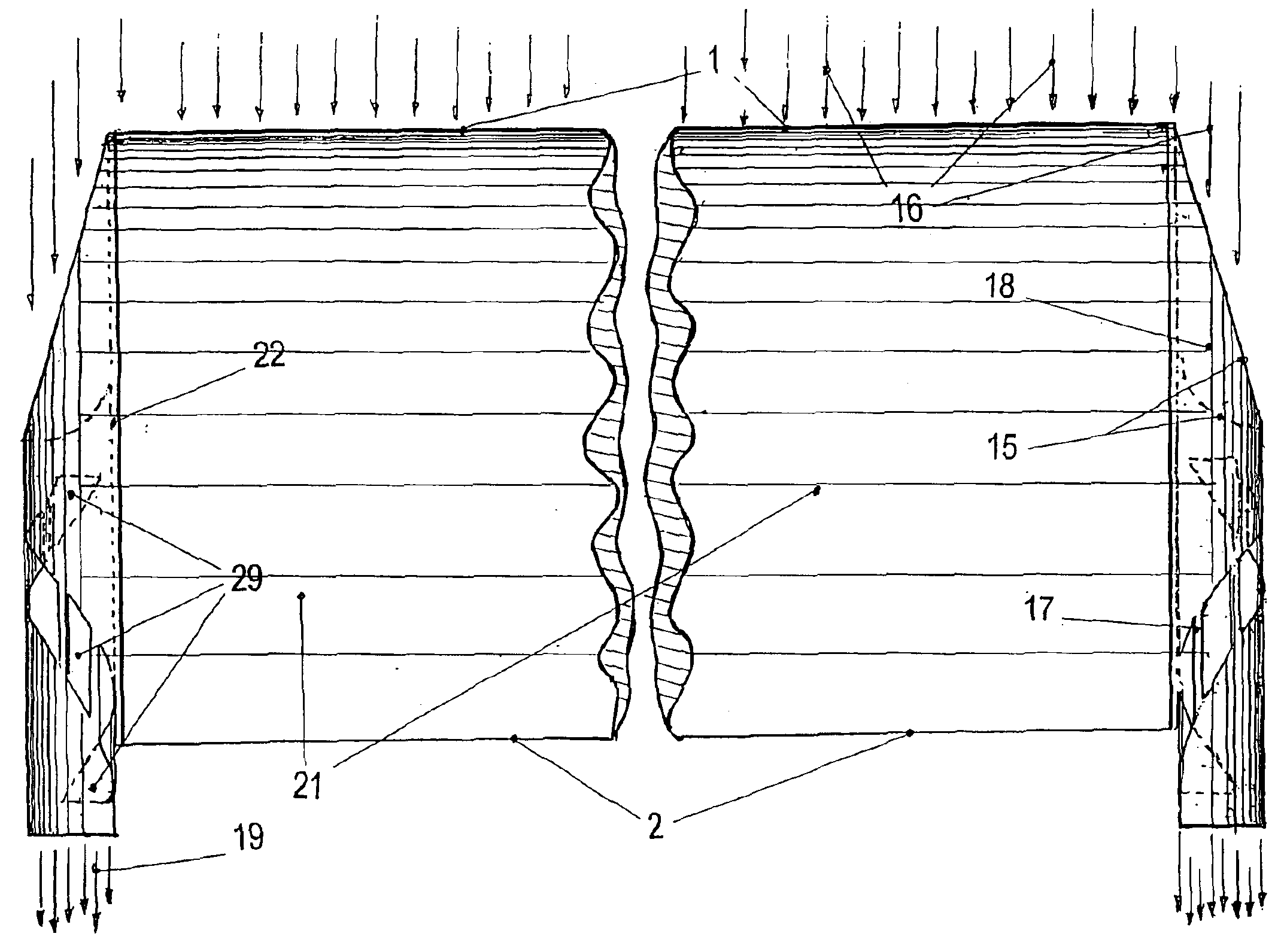
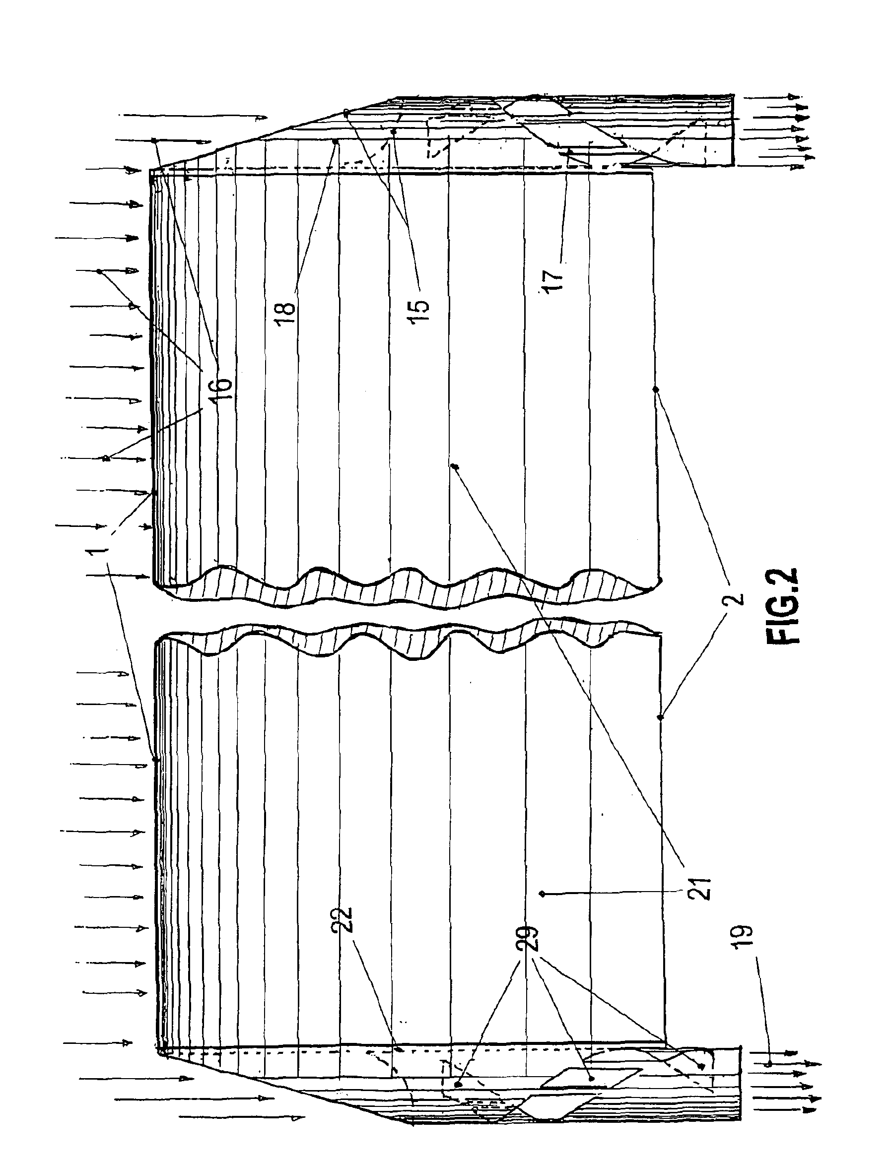
[0084]Side view of the device secured to the wingtip: forming an integral part as a continuation of the cylinder with its helicoidal slot, and having the same diametrical curvature, the small tongue (18), a kind of semi-circular ovoid in the form of a cut goose feather, follows the shape of the upper surface of the wing towards and up to the leading edge (1). The complete system, whether fixed or mobile, can move parallel to the airfoil chord (6) towards the leading edge (1) or trailing edge (2), and can have a negative or positive setting according to flight data.

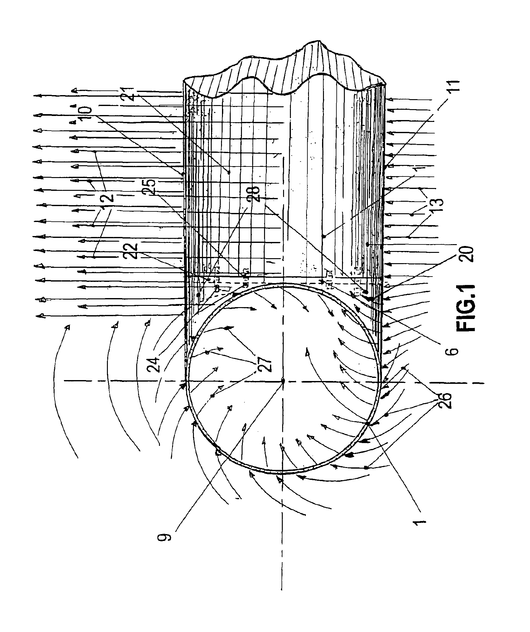
[0085]Overhead view of the device secured to the wingtip on the upper surface (10): commencing on the upper surface of the leading edge (1), the small tongue (18) broadens following the same curvature as the device, forming a semi-circle integral with the cylindrical inlet with the helicoidal slot.

[0086]Front view of the leading edge with the device secured to the wingtip: the small tongue (18) (foreground) with the same d...


PUM


Abstract

A device having the form of a cylindrical spiral cavity and/or incorporating a helicoidal slot, making it possible to reduce induced drag and marginal swirl (vortex) and increase drag/lift ratio. Integrated with the wingtip or articulated on the wingtip, it can be adapted for all airfoils, in particular the wings of airplanes and gliders, helicopter blades and the tips or tractor or pusher airscrews, wind-powered generator blades and for surface vessels or submarines where lift or direction is used in triple axis (vertical, horizontal, and yaw) displacement. Used in a reverse configuration (undersurface/upper surface) on high speed land vehicles or racing cars, this device, when secured to the tip of each wing, produces a result inversely proportional to speed. The faster the vehicle is traveling, the less drag it generates and greater its ground adhesion.

Description

BACKGROUND OF THE INVENTION[0001]1. Field of the Invention[0002]Secured to a wingtip, the invention concerns a device having the shape of a goose feather cut outwards and towards the leading edge, the shank of which represents a cylindrical cavity spiral in form and / or incorporating a helicoidal slot. The device reduces induced drag and marginal swirl (vortex), and increases lift-drag ratio.[0003]Secured to the wingtip, articulated or not, the device can be adapted for all airfoils, in particular the wings of airplanes and gliders, helicopter blades and the tips of tractor and pusher airscrews or the blades of wind-powered generators, and also for surface vessels or submarines, where lift or direction is used in triple-axis (vertical, horizontal and yaw) displacement.[0004]In terms of initial performance, the invention provides for lower power drive systems, increased range and higher speeds, while reducing energy consumption or producing increased energy in the case of wind-powered...

Claims


Application Information

Patent Timeline
IPC IPC(8): B64C23/00B64C23/06
CPCB64C23/065Y02T50/164Y02E10/721Y02E10/72Y02T50/10
Inventor HUGUES, CHRISTIAN
Owner HUGUES CHRISTIAN
Why Eureka
Try Eureka