System and method for active detection of connection to a network

a network and active detection technology, applied in the field of digital computing equipment, can solve the problems of affecting the performance of the modem, the circuitry needed to establish the network connection in the transceiver is disabled, and the power used by the transceiver is large enough to unsatisfactory reduce the battery life of portable computers, etc., to achieve the effect of quick powering up the transceiver and efficient and elegant structure and method

Inactive Publication Date: 2005-05-17
INTEL CORP
View PDF21 Cites 39 Cited by
  • Summary
  • Abstract
  • Description
  • Claims
  • Application Information

AI Technical Summary

Benefits of technology

[0025]The present invention provides an efficient and elegant structure and method for detecting the presence of an active connection to a data transmission network. The present invention functions by detecting the network signal energy on a network medium, such as a network cable. The present invention solves the problems of excessive power consumption and generation of excessive electrical noise. The embodiments of the present invention give an indication of whether or not an active network connection is present on a network cable. Advantageously, the embodiments of the present invention do not attempt to create a network connection; The embodiments of the present invention monitors the receive network lines to determine if there is electrical energy on the cable in the form particular to the type of network supported...

Problems solved by technology

The amount of power used by the transceiver is great enough to unsatisfactorily reduce the battery life of portable computers when being powered from the internal battery.
In addition, because network and modem components on a combination network/modem card are in such close proximity, the constant attempts of the transceiver to find a network connection creates electrical noise that can adversely interfere and affect modem performance since the circuit board in the PC Card contains the components for both the modem and the network adaptor.
However, the circuitry needed to establish a network connection is disabled in a transceiver when the transceiver is in the low-power mode.
While it has been suggested that it is possible to put the transceiver into the low-power mode and periodically give it full power to check for a cable being ...

Method used


Image

  • System and method for active detection of connection to a network
  • System and method for active detection of connection to a network
  • System and method for active detection of connection to a network

Examples


Embodiment Construction

[0036]Reference will now be made to the drawings wherein like structures will be provided with like reference designations.

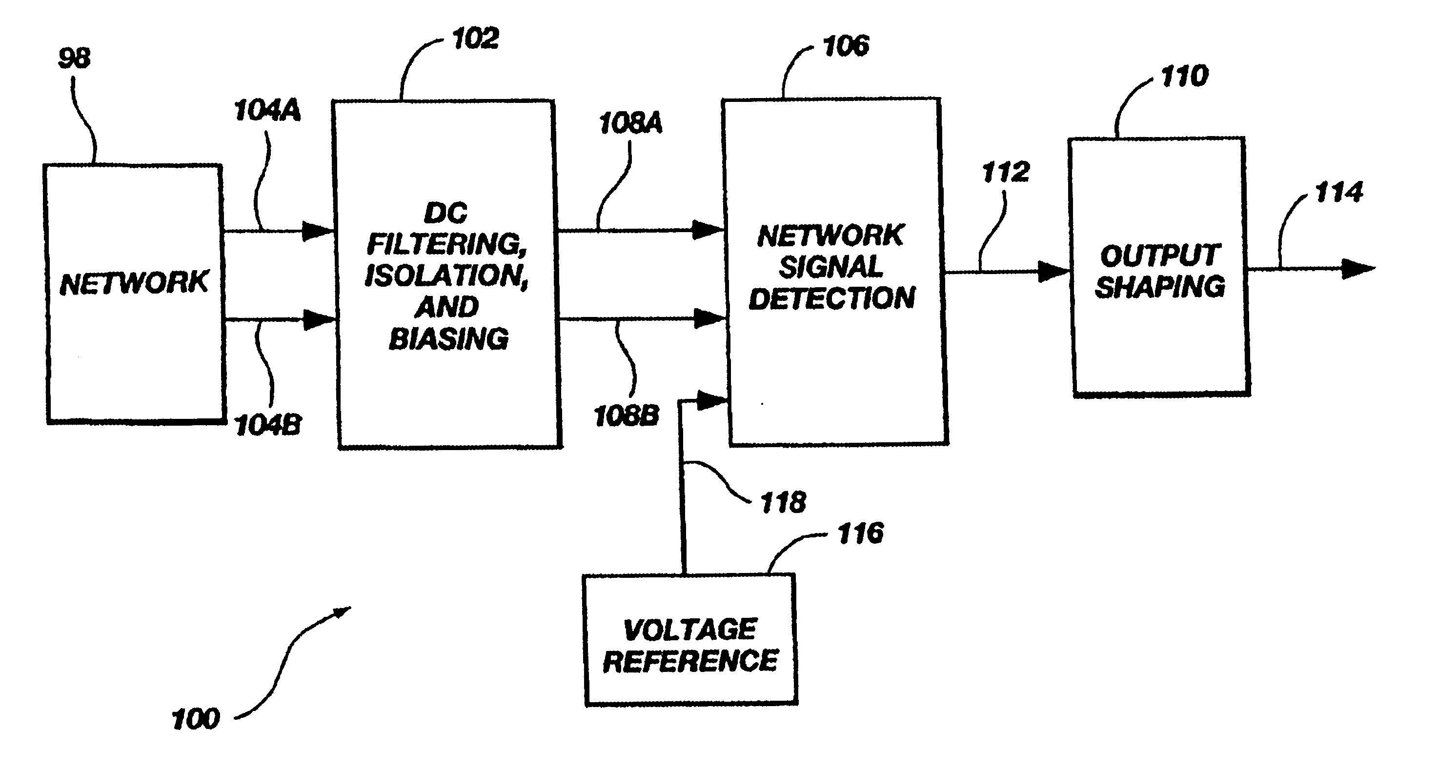
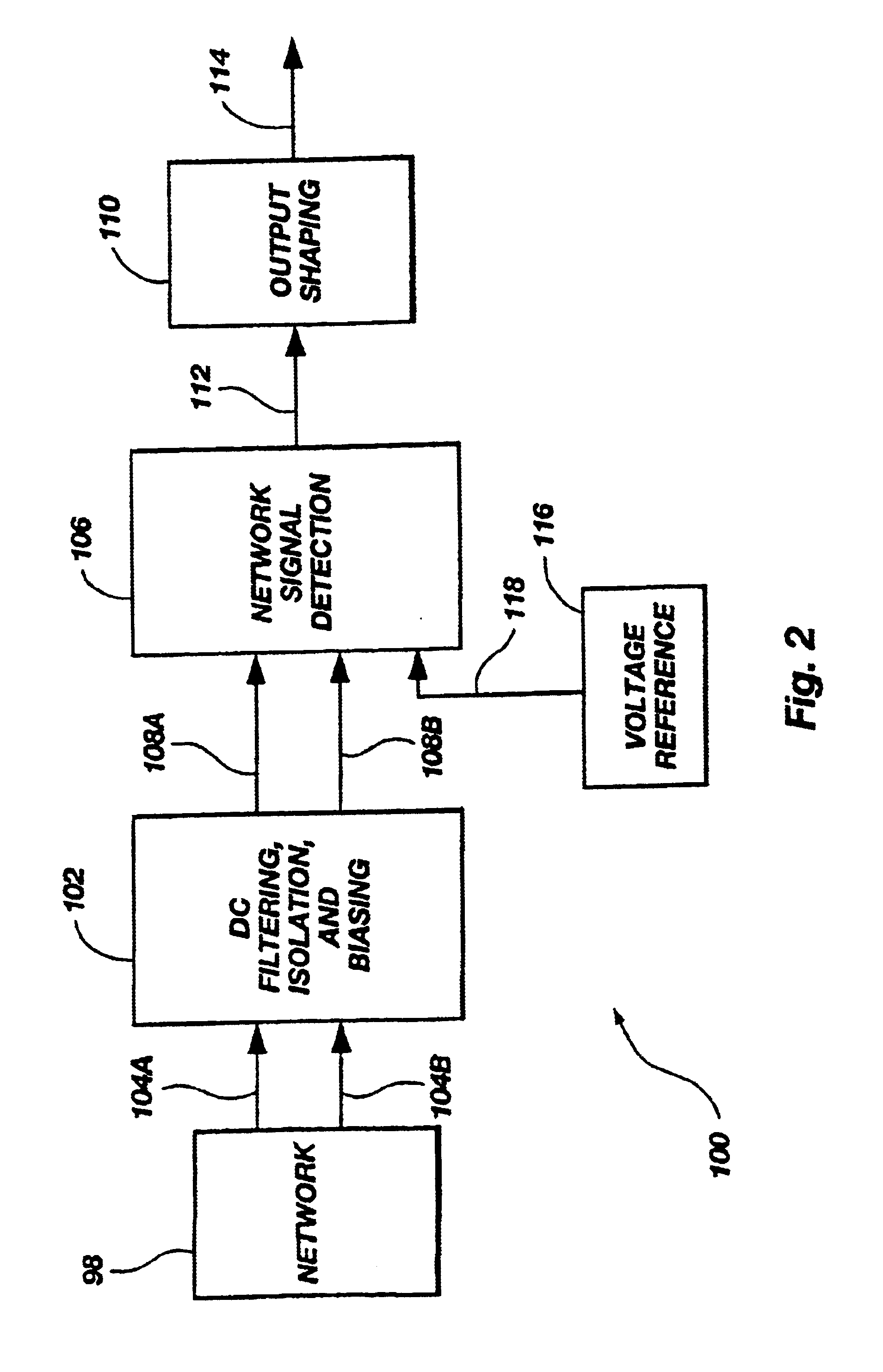
[0037]Reference will first be made to FIG. 2 which is a block diagram showing the configuration of a presently preferred embodiment of the present invention, generally indicated at 100. It will be appreciated that the block diagram represented in FIG. 2 is merely exemplary of the present invention and is not intended to be limiting of the scope of the present invention. Those skilled in the art will appreciate that many different components and configurations can be arrived at to carry out the present invention. Moreover, all structures, whether now know or which become known in the future, which perform functions which are similar or equivalent to the functions carried out by the structures represented in FIG. 2 are intended to fall within the scope of the present invention.

[0038]Represented in FIG. 2 is a network 98, which is preferably a network complying wit...


PUM


Abstract

An apparatus and method for detecting a connection to a data transmission network functions by detecting the network signal energy on a network cable while avoiding the problems of excessive power consumption and generation of excessive electrical noise. By monitoring the receive network lines and determining if there is electrical energy on the cable in the form particular to the type of network supported by the network adaptor card, the host computing device can power-down the transceiver associated with the network adaptor card until an active network connection is detected.

Description

[0001]This application is a continuation of prior application Ser. No. 09 / 437,545 filed Nov. 10, 1999 (abandoned), which is a continuation of prior application Ser. No. 09 / 050,290 filed Mar. 30, 1998, now U.S. Pat. No. 6,169,475, issued on Jun. 2, 2001.BACKGROUND[0002]1. The Field of the Invention[0003]This invention relates to digital computing equipment. More particularly, the present invention relates to devices used to interconnect computing equipment in a network configuration.[0004]2. Background of Invention Information[0005]The proliferation of computers has made great computing power available to large numbers of users. The flexibility and capabilities of personal computers is greatly enhanced when the computers are interconnected to each other. When a plurality of computers are interconnected to share information, it is generally referred to as a network. Local Area Networks (LANs) are those networks which connect computers over a relatively small geographic areas and Wide ...

Claims


Application Information

Patent Timeline
IPC IPC(8): G08B17/10G08B9/00G06F1/32G08B23/00H04L12/26H04L12/28H04L12/40H04L29/00
CPCH04M11/066
Inventor BROWNING, KURT R.
Owner INTEL CORP
Why Eureka
Try Eureka