Method and apparatus for processing video pictures

a technology for processing apparatus and video pictures, applied in the field of video picture processing methods and apparatuses, can solve the problem of not having enough video levels to have a good video quality, and achieve the effect of increasing the grey scale portrayal and being very easy to implemen

Inactive Publication Date: 2005-05-17
INTERDIGITAL CE PATENT HLDG
View PDF5 Cites 23 Cited by
  • Summary
  • Abstract
  • Description
  • Claims
  • Application Information

AI Technical Summary

Benefits of technology

[0013]According to the claimed solution in claim 1, a new type of sub-field coding is used based on a sub-field organization with n sub-fields, in which among the set of p possible video levels for a colour component a sub-set of m video levels is selected with n<m<p wherein the m values are selected according to the rule that the temporal centre of gravity for the light generation of the corresponding sub-field code words grows continuously apart from exceptions in the low video level range up to a first predefined limit and / or in the high video level range from a second predefined limit on. While according to the incremental coding described above only very few video levels are admissible for sub-field coding, namely as much as sub-fields are available in the sub-field organization, the sub-field coding method according to the invention relies on more video levels and thus provides for a better grey scale rendition and less disturbing dithering noise. The admissible video levels according to the inventive solution cannot be arbitrarily taken from the full video level range but are selected with a specific rule, namely that the temporal centre of gravity of admissible sub-field code words grows smoothly when the video levels are ordered according to size. There are only some exceptions allowable in the low video level range and in the high video level range.
[0018]It is very advantageous, if the sub-field coding process respects the rule that for all input video levels that are different from zero a sub-field code word is selected, in which never more than one consecutive sub-field is inactivated between two activated sub-fields. This rule drastically reduces the number of possible sub-field code words, so that for setting up the sub-set of m video levels the choice of video levels and corresponding sub-field code words is simplified. Taking only those sub-field code words and corresponding video levels respecting above mentioned rule has the additional advantage that the response fidelity of the plasma cells in case of a plasma display panel is subjectively increased. This is because the distance in time between two writing periods for a plasma cell is reduced, so that the probability of a correct pre-charging of the plasma cell during the writing period is increased. With sub-field coding methods not respecting this rule the problem can arise that some plasma cells show some sort of flickering because they are not correctly lighted in each video frame.
[0020]As the plasma display panels have a linear response characteristic, it is advantageous to provide a Degamma unit, in which the input video levels are compensated for the gamma correction in the video source.
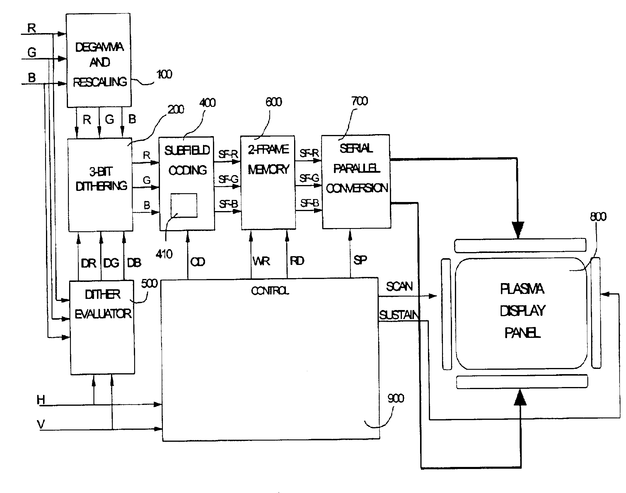
[0021]Also it is advantageous to provide a dithering unit, in which dithering values are added to the output values of the Degamma unit to increase the grey scale portrayal. As known from the dithering technique, in the dithering unit a truncation of the video level data is performed to the bit resolution, which is required for the number m of video levels in the selected sub-set. This video level data is input to the look-up table for the sub-field coding process. This look-up table can be designed to not include the sub-field code word but instead the full resolution video level word (preferably 8 bit). This allows implementing the dynamic false contour compensation method at the video level processing stage, i.e. before sub-field coding so that the method can be simply implemented very easily on any panel type.

Problems solved by technology

It is not possible to select video levels with growing gravity centre in the low level range because the number of possible video levels is low and so if only smoothly growing centre of gravity levels where selected, then there would not be enough video levels to have a good video quality in the black / dark video levels, since the human eye is very sensitive in the dark / black level range.

Method used


Image

  • Method and apparatus for processing video pictures
  • Method and apparatus for processing video pictures
  • Method and apparatus for processing video pictures

Examples


Embodiment Construction

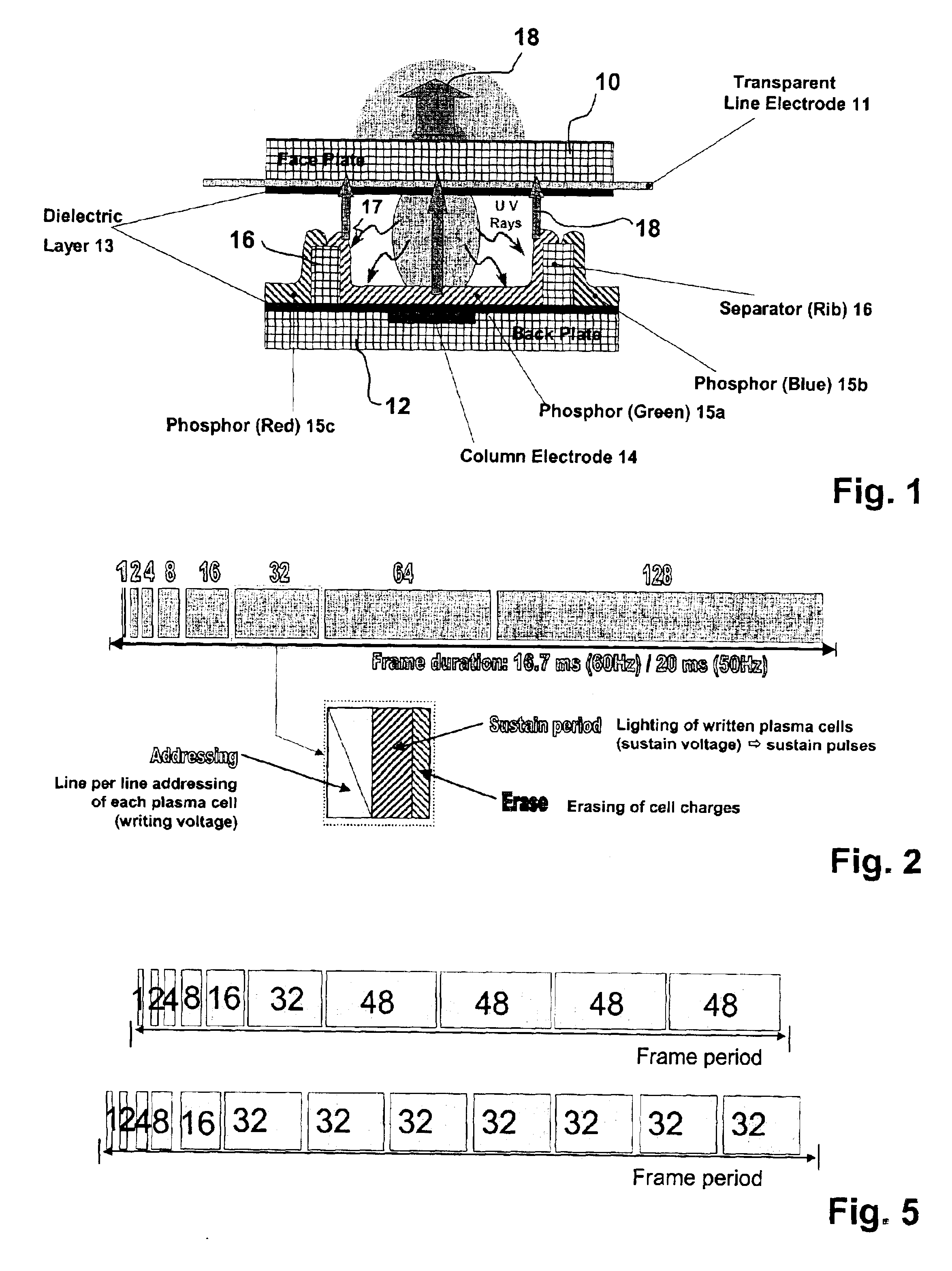
[0040]The principle structure of a plasma cell in the so-called matrix plasma technology is shown in FIG. 1. Reference number 10 denotes a face plate made of glass, with reference number 11 a transparent line electrode is denoted. The back plate of the panel is referenced with reference number 12. There are 2 dielectric layers 13 for isolating face and back plate against each other. In the back plate column electrodes 14 are integrated being perpendicular to the line electrodes 11. The inner part of the cells consists of a luminance substance 15 (phosphorous) and separator 16 for separating the different coloured phosphorous substances (green 15a) (blue 15b) (red 15c). The UV radiation caused by the discharge is denoted with reference number 17. The light emitted from the green phosphorous 15a is indicated with an arrow having the reference number 18. From this structure of a PDP cell it is clear that there are three plasma cells necessary, corresponding to the three colour componen...


PUM


Abstract

A method and apparatus for processing video pictures for dynamic false contour effect compensation is provided wherein the video picture consists of pixels having at least one color component (RGB) the color component values being digitally coded with a digital code word, hereinafter called sub-field code word (SF-R, SF-G, F-B). To each bit of a sub-field code word (SF-R, SF-G, SF-B) a certain duration is assigned hereinafter called a sub-field, during which a color component of the pixel can be activated for light generation. The digital code words have n bits, characterized in that among a set p possible video levels for the at least one color component (RGB) a sub-set of m video levels with n<m<p is selected, which is used for light generation. The m values are selected according to the rule that the temporal center of gravity (CG1, CG2, CG3) for the light generation of the corresponding sub-field code words grow continuously with the video level, apart from possible exceptions in the low video level range up to a first predefined limit and / or in the high video level range from a second predefined limit on.

Description

BACKGROUND OF THE INVENTION[0001]The invention relates to a method and apparatus for processing video pictures, especially for dynamic false contour effect compensation. This method and apparatus is usable in display devices, such as matrix displays like plasma display panels (PDP), display devices with digital micro mirror arrays (DMD) and all kinds of displays based on the principle of duty cycle modulation (pulse width modulation) of light generation.[0002]The plasma display technology now makes it possible to achieve flat colour panels of large size and with limited depth without any viewing angle constraints. The size of the displays may be much larger than the classical CRT picture tubes would have ever allowed.[0003]A plasma display panel utilizes a matrix array of discharge cells, which could only be “on” or “off”. Also unlike a CRT or LCD in which grey levels are expressed by analogue control of the emission, a PDP controls the grey levels by modulating the number of light ...

Claims


Application Information

Patent Timeline
Patent Type & Authority Patents(United States)
IPC IPC(8): G09G3/28G09G3/20H04N5/66G09G3/34
CPCG09G3/2029G09G3/2803G09G3/2051G09G2320/0266G09G2320/0261G09G3/291G09G3/296
Inventor THEBAULT, CEDRICCORREA, CARLOSWEITBRUCH, SEBASTIEN
Owner INTERDIGITAL CE PATENT HLDG
Why Eureka
Try Eureka