
Power capacitor

Inactive Publication Date: 2005-05-17
ABB POWER GRIDS SWITZERLAND AG
View PDF13 Cites 16 Cited by
  • Summary
  • Abstract
  • Description
  • Claims
  • Application Information

AI Technical Summary

Benefits of technology

[0035]Yet another preferred use is utilizing the power capacitor in a capacitor voltage divided in a capacitor voltage transformer. With the compactness and simplicity obtained with the power capacitor in accordance with this embodiment of the invention, the area of application for using the capacitor for voltage transforming increases.
[0036]In accordance with another preferred use, one or more power capacitors in accordance with the invention is/are utilized as voltage-rigid static current changer/inverter. An important area of application for these is in high-voltage direct current transmission (HVDC). Such transmission has for a long time been used almost exclusively for transmitting extremely high power long distances. Recently, however, voltage-rigid inverters have come into use for HVDC. This, together with the used of metal oxide semiconductors instead of thyristor rectifiers, has lead to an increase in the economically reasonable area for HVDC transmission down to a single megawatt. Thanks to its favorable properties such as compactness, simplicity and low cost, a power capacitor in accordance with this embodiment of the invention contributes to further increasing the area of application for HVDC transmission and to it being a more competitive alternative than conventional alternating current transmission and local generation in remotely situated communities. This technique also ope

Problems solved by technology

This problem is particularly pronounced when the capacitor bank consists of a large number of capacitors.
Long cables for alternating voltage are inductive and consume reactive power.
The mechanical resonance frequency of the stack is amplified by specific frequencies of the current, which may produce a loud noise.
None of these, however, relates to a power capacitor for high voltage.
One problem with a capacitor of known type, e.g. of the type described in U.S. Pat. No. 5,475,272 mentioned above, is that the capacitor elements included must be insulated from the container.
Their external, flattened shape is unfavorable with regard to

Method used


Image

  • Power capacitor
  • Power capacitor
  • Power capacitor

Examples


Example

DETAILED DESCRIPTION OF THE DRAWINGS

[0063]Referring now to the drawings, wherein like reference numerals designate identical or corresponding parts throughout the several views.

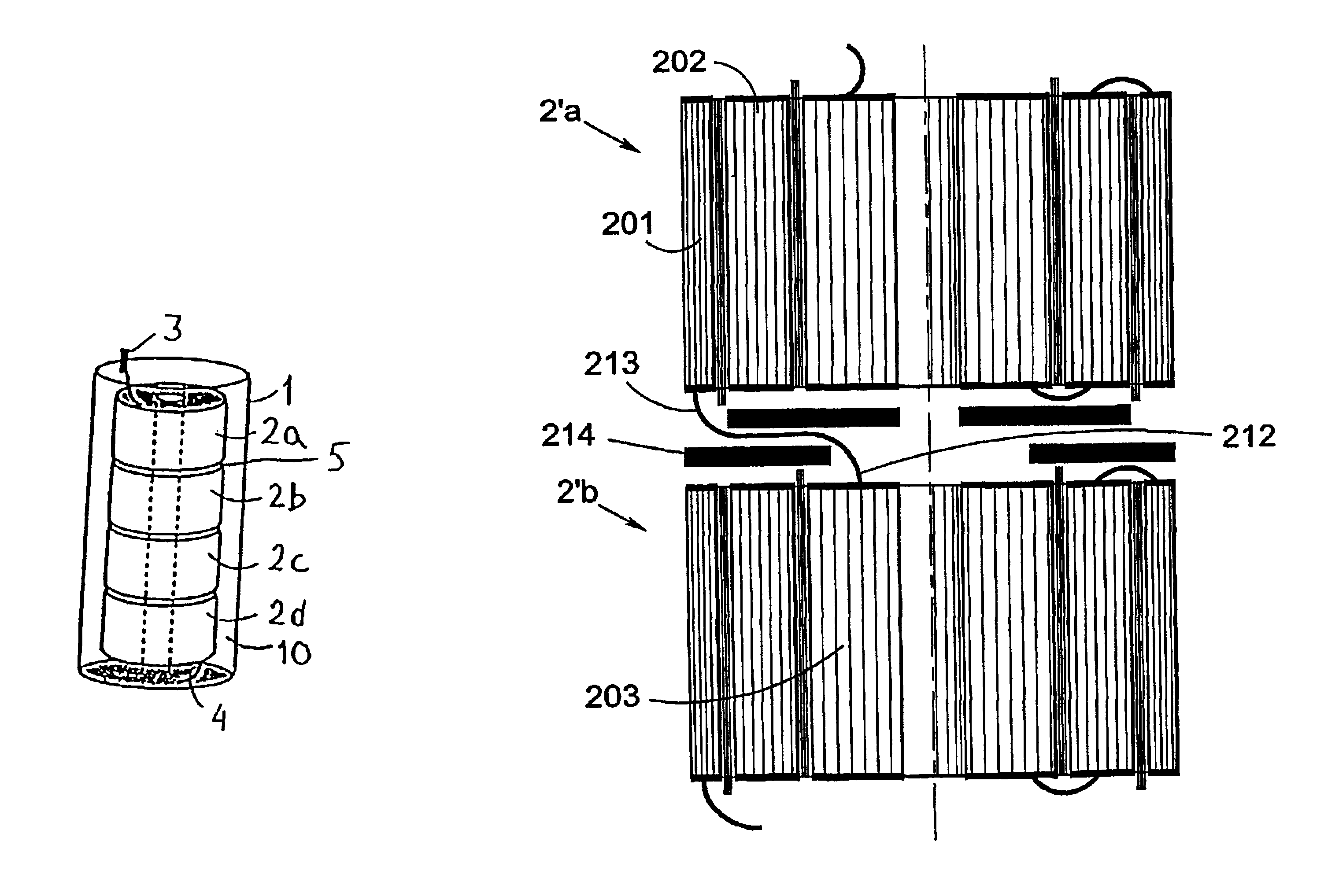
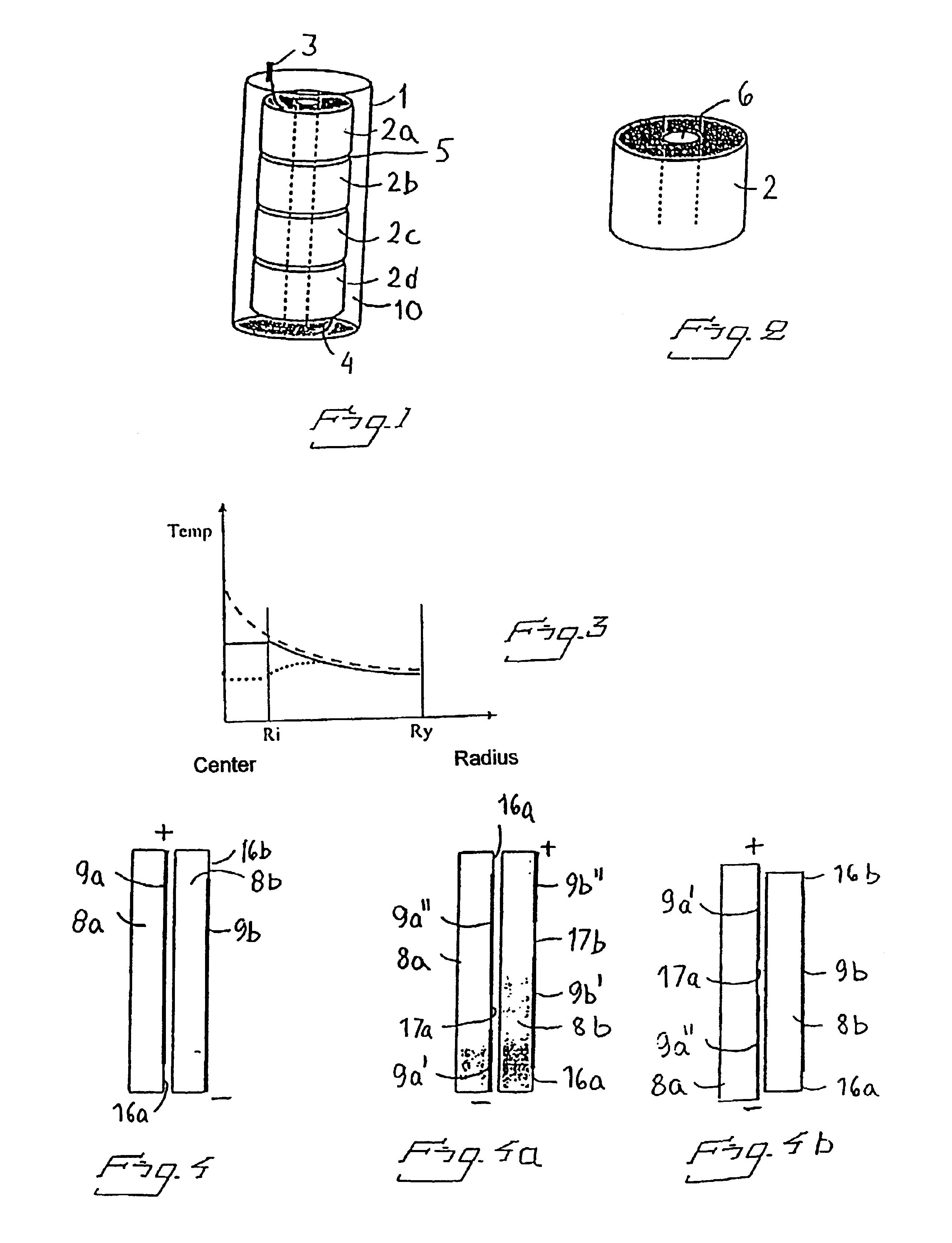
[0064]FIG. 1 shows in principle the design of a capacitor in accordance with the invention. It consists of an outer container 1 of polyethylene which encloses, in this case, four capacitor elements 2a-2d. The container 1, like the capacitor elements 2a-2d, is circular-cylindrical. The capacitor elements 2a-2d are connected in series. Connection terminals 3, 4 are arranged at each end of the capacitor. Each terminal consists of a conducting foil mounted in the material of the container and extending therethrough. A gel 10 is arranged between the capacitor elements 2a-2d and the container. The gel serves as electrical insulation and thermal conductor.

[0065]FIG. 2 shows an individual capacitor element comprising metal-coated polymer films tightly rolled to a roll. The capacitor element 2 has an axially running h...


PUM


Abstract

A power capacitor for high voltage and including at least one capacitor element that has improved electrical properties and that allows simple manufacture. Each capacitor element has a substantially circular-cylindrical shape. The inside of the container has a corresponding shape to closely surround each capacitor element. In addition, each capacitor element is oriented with the axial direction coinciding with the axial direction of the container. A capacitor bank includes a plurality of the power capacitors, and uses of one or more of the invented power capacitors can be used as a component in electrical installations.

Description

BACKGROUND OF THE INVENTION[0001]1. Field of the Invention[0002]The present invention relates to a power capacitor primarily intended for a rated voltage in excess of 1 kV, .e.g. 5 kV, preferably at least 10 kV. The present invention also relates to a capacitor bank having a plurality of power capacitors.[0003]2. Description of the Background Art[0004]Power capacitors are important components in systems for transmission and distribution of electric power. Power capacitor installations are used primarily to increase power transmission capability through parallel and series compensation, for voltage stabilisation through static var-systems, and as filters for eliminating harmonics.[0005]Capacitors have a phase angle that is close to 90° and therefore generates reactive power. By connecting a capacitor in the vicinity of the components that consume reactive, power, the desired reactive power can be generated there. Cables can thus be utilized to the full extent for transmitting active ...

Claims


Application Information

Patent Timeline
IPC IPC(8): H01G4/38H01G4/224H01G4/18
CPCH01G4/224H01G4/18H01G4/38
Inventor ERIKSSON, ESBJORNDRUGGE, BIRGERHOLMGREN, TOMMYFRISK, GORAN
Owner ABB POWER GRIDS SWITZERLAND AG
Learn More